Eureka AIR delivers breakthrough ideas for toughest innovation challenges, trusted by R&D personnel around the world.

Adaptable transponder for multiple telemetry systems

Active Publication Date: 2014-06-17
NASA
View PDF1 Cites 1 Cited by
  • Summary
  • Abstract
  • Description
  • Claims
  • Application Information

AI Technical Summary

Benefits of technology

The present invention is a telemetry transponder system that is made up of interchangeable decks that house telemetry components. These decks are designed to be quickly and easily replaced, allowing for the creation of a functional transponder for a range of telemetry systems on a time-sensitive and low-cost basis. The invention also includes a Forward Error Correcting protocol, a Low Pass Filter, and a radio frequency baseband filter, which are important components of data transmission and signal processing. The technical effects of this invention include improved efficiency, flexibility, and cost-effectiveness for telemetry systems.

Problems solved by technology

A primary cost associated with development and customization of transponders and telemetry systems is the configuration and development of error checking components.
An additional problem known in the art is the need for strict quality control protocols or “prequalification” of each component used by NASA.
The qualification process is extremely costly and generally requires that a new device be tested in a NASA lab or have been previously used in flight.
The qualification process limits the availability of transponders designed to interface with rapidly evolving and diverse telemetry systems including lunar missions and missions to Mars, military intelligence, wireless internet, cellular telephones, climate change studies, and emergency services such as fire, ambulance and police.

Method used


Image

  • Adaptable transponder for multiple telemetry systems
  • Adaptable transponder for multiple telemetry systems
  • Adaptable transponder for multiple telemetry systems

Examples


Embodiment Construction

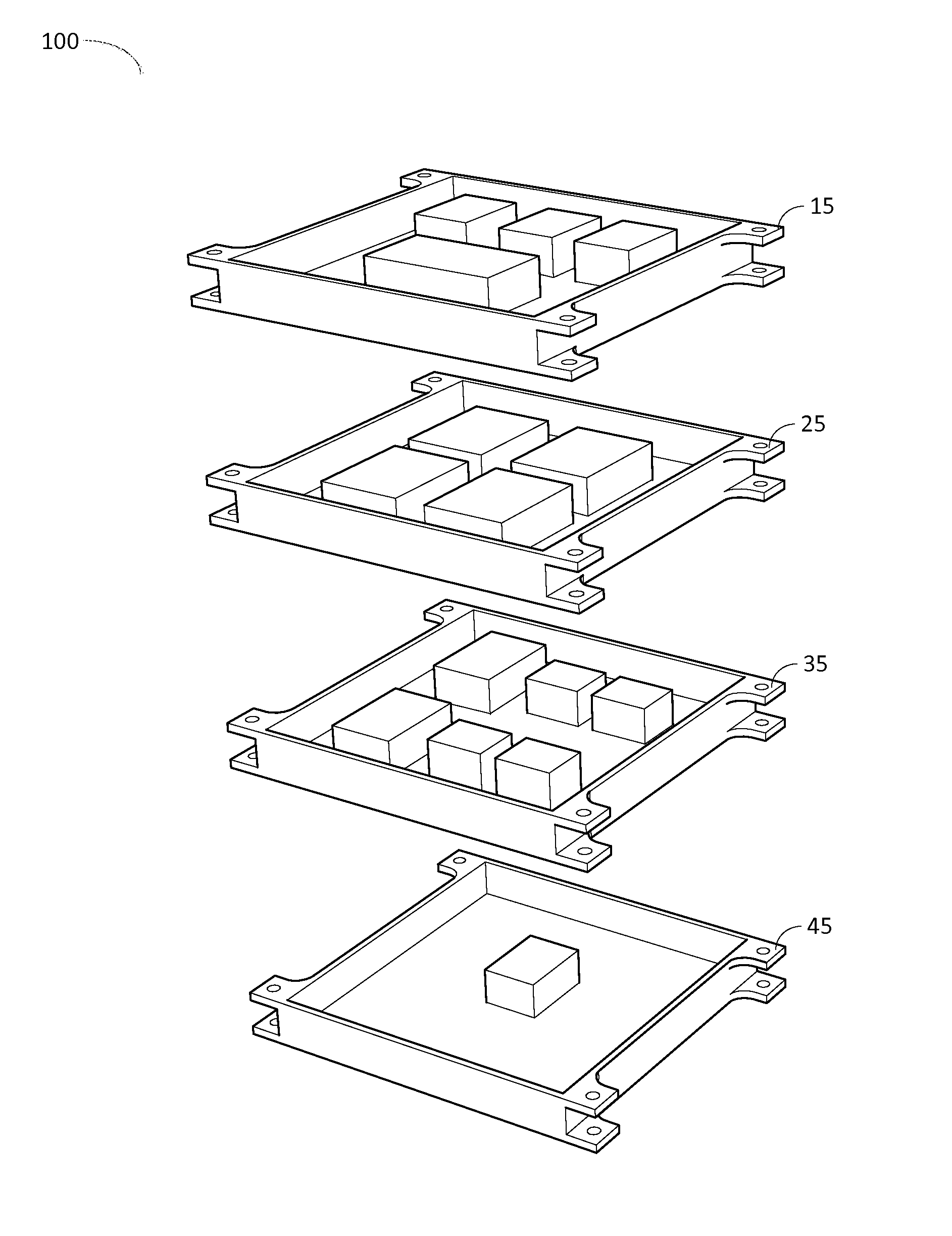
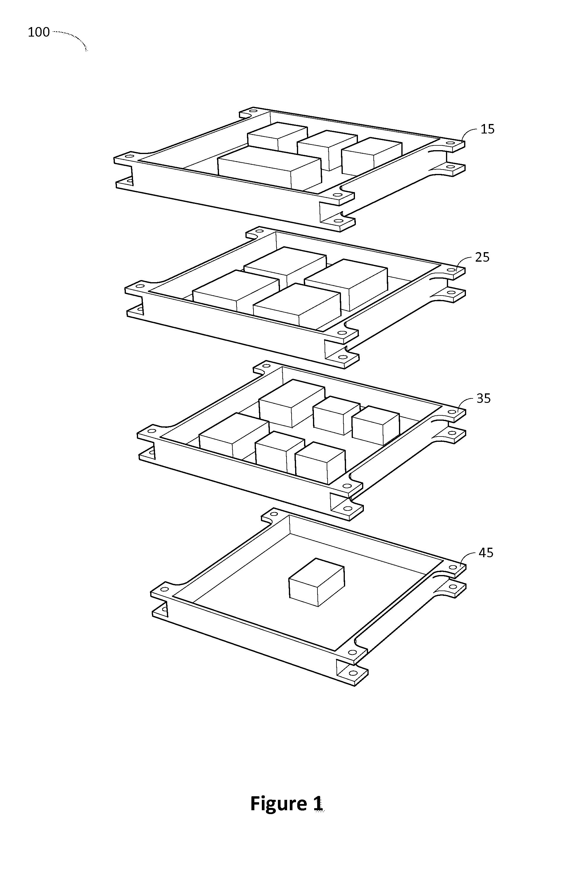
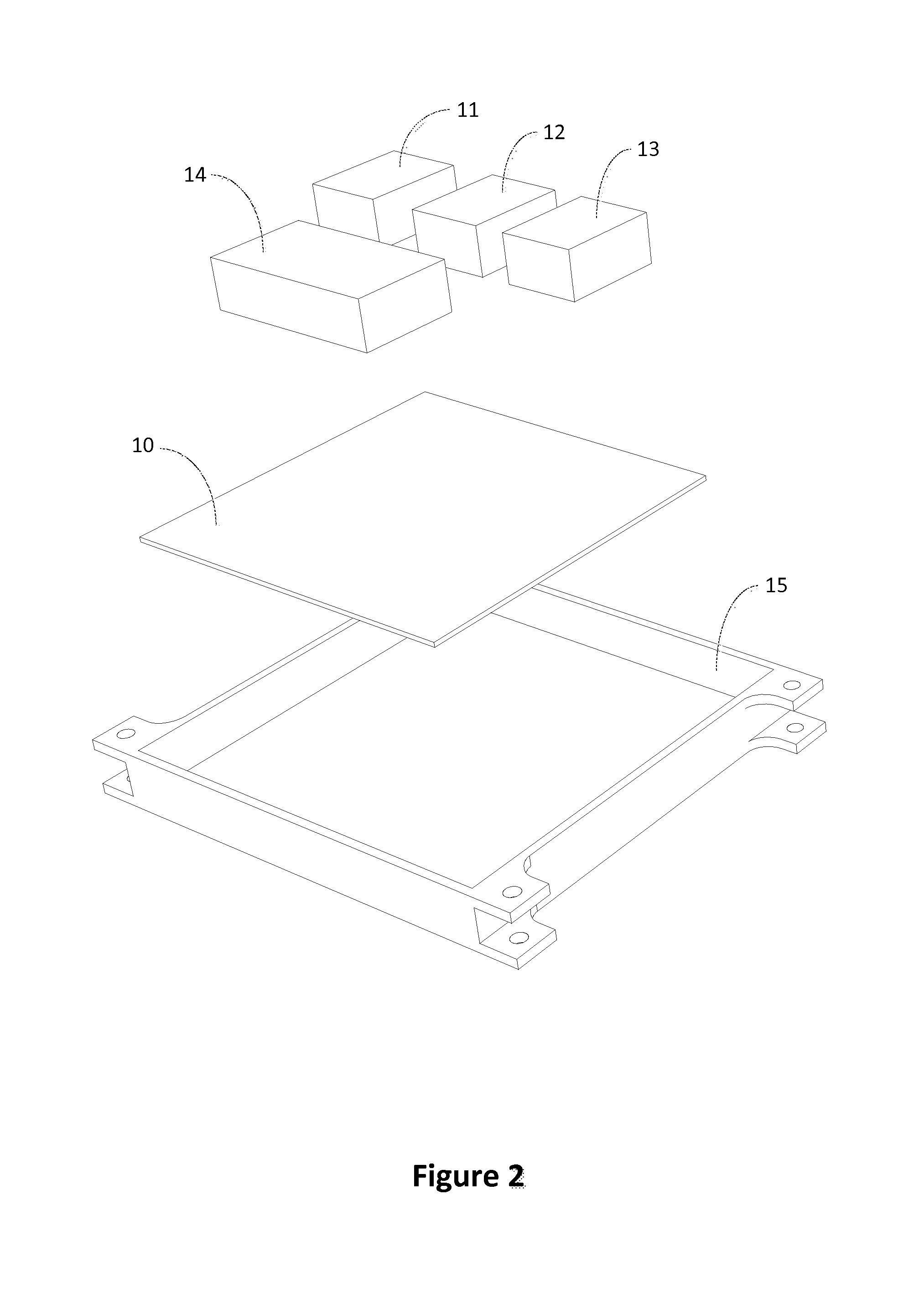
[0044]For the purpose of promoting an understanding of the present invention, references are made in the text to exemplary embodiments of a telemetry system which utilizes interchangeable prequalified decks and associated components, only some of which are described herein. It should be understood that no limitations on the scope of the invention are intended by describing these exemplary embodiments. One of ordinary skill in the art will readily appreciate that alternate but functionally equivalent components, materials, and placement may be used. The inclusion of additional elements may be deemed readily apparent and obvious to one of ordinary skill in the art. Specific elements disclosed herein are not to be interpreted as limiting, but rather as a basis for the claims and as a representative basis for teaching one of ordinary skill in the art to employ the present invention.

[0045]It should be understood that the drawings are not necessarily to scale; instead, emphasis has been p...


PUM


Abstract

The present invention is a stackable telemetry circuit board for use in telemetry systems for satellites and other purposes. The present invention incorporates previously-qualified interchangeable circuit boards, or “decks,” that perform functions such as power, signal receiving and transmission, and processing. Each deck is adapted to serve a range of telemetry applications. This provides flexibility in the construction of the stackable telemetry circuit board and significantly reduces the cost and time necessary to develop a telemetry system.

Description

FEDERAL RESEARCH STATEMENT[0001]The invention described herein was made by employees of the United States Government and may be manufactured and used by or for the Government of the United States of America for governmental purposes without the payment of any royalties thereon or therefore.FIELD OF INVENTION[0002]The present invention relates to the field of satellite telemetry systems, and more specifically to a modularly designed transponder device that can be rapidly configured for use with any telemetry system.BRIEF DESCRIPTION OF THE DRAWINGS[0003]FIG. 1 illustrates an isometric view of exemplary embodiment of a stackable telemetry circuit board apparatus.[0004]FIG. 2 illustrates an exemplary embodiment of a receiver deck for a stackable telemetry circuit board.[0005]FIG. 3 is an exemplary embodiment of a processor deck for stackable telemetry circuit board.[0006]FIG. 4 is an exemplary embodiment of a transmitter deck for a stackable telemetry circuit board.[0007]FIG. 5 is an e...

Claims


Application Information

Patent Timeline
IPC IPC(8): G01S13/08
CPCG01S13/08G01S2007/027H04B7/18515H04B7/185G01S7/027
Inventor SIMS, III, WILLIAM HERBERTVARNAVAS, KOSTA A.
Owner NASA
Why Eureka
Eureka Blog
Learn More