
Crosstalk compensation in analysis of energy storage devices

a technology of energy storage device and crosstalk compensation, which is applied in the direction of noise figure or signal-to-noise ratio measurement, instruments, digital computer details, etc., can solve the problems of insufficient monitoring of simple parameters such as voltage, current and temperature to gauge the remaining capacity of the energy storage device, data may be contaminated, and the resolution of frequencies cannot be any finer

Active Publication Date: 2014-06-24
BATTELLE ENERGY ALLIANCE LLC
View PDF30 Cites 20 Cited by
  • Summary
  • Abstract
  • Description
  • Claims
  • Application Information

AI Technical Summary

Benefits of technology

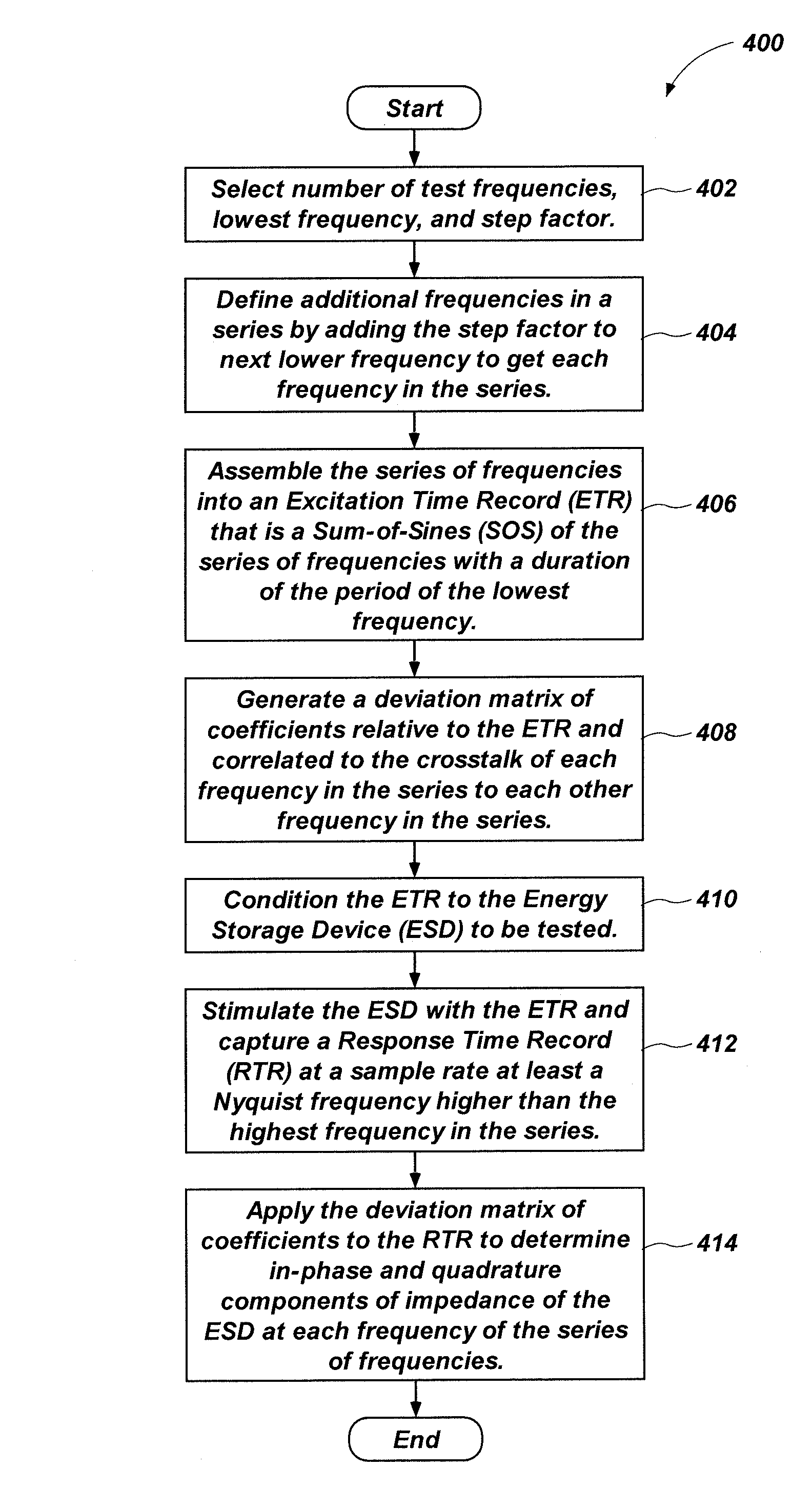
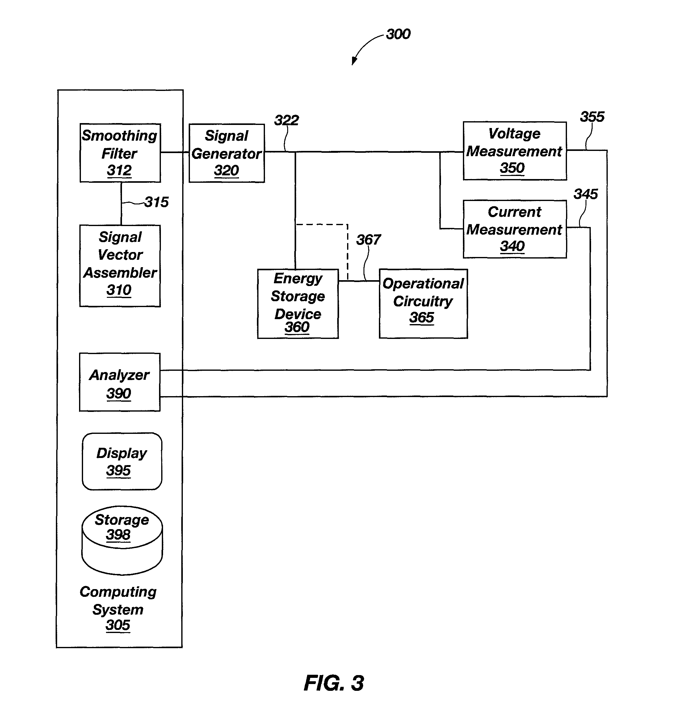
This patent describes a method for generating input signals at different frequencies with a frequency step factor between them, and using these signals to excite an energy storage device. The system then captures the device's response time record to determine its impedance at each frequency. A deviation matrix is applied to the response record to remove crosstalk between the different frequency signals, resulting in new response signals that are more accurate and reliable. Overall, this method allows for better control and analysis of the energy storage device's response to different frequencies of input signals.

Problems solved by technology

For many applications, however, it is insufficient to monitor simple parameters such as voltage, current, and temperature to gauge the remaining capacity of the energy storage device.
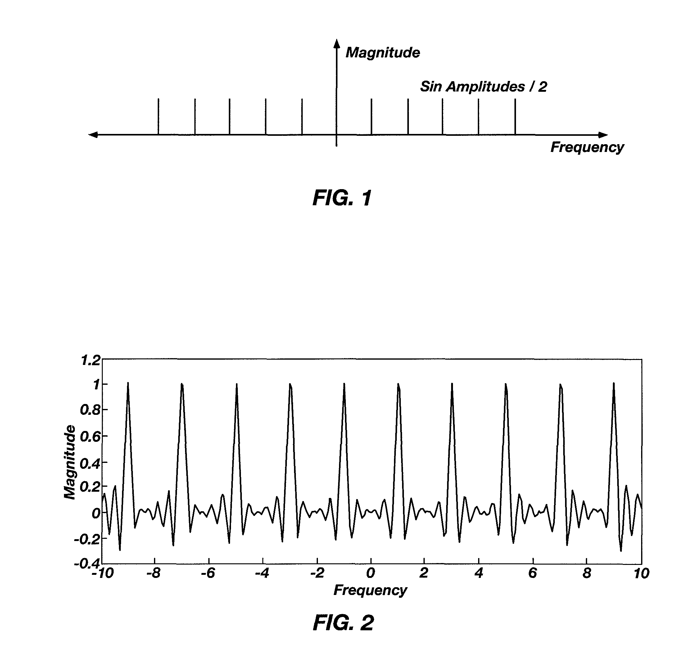
However, these data may be tainted by crosstalk error, so the response signal is reassembled with all the frequencies except the one of interest, and then subtracted from the original response signal and synchronously detected again.
However, with FST the resolution in frequencies cannot be any finer than octave steps.

Method used


Image

  • Crosstalk compensation in analysis of energy storage devices
  • Crosstalk compensation in analysis of energy storage devices
  • Crosstalk compensation in analysis of energy storage devices

Examples


Embodiment Construction

[0024]In the following description, reference is made to the accompanying drawings that form a part hereof, and in which is shown, by way of illustration, specific embodiments in which the disclosure may be practiced. The embodiments are intended to describe aspects of the disclosure in sufficient detail to enable those skilled in the art to practice the invention. Other embodiments may be utilized and changes may be made without departing from the scope of the disclosure. The following detailed description is not to be taken in a limiting sense, and the scope of the present invention is defined only by the appended claims.

[0025]Furthermore, specific implementations shown and described are only examples and should not be construed as the only way to implement the present disclosure unless specified otherwise herein. It will be readily apparent to one of ordinary skill in the art that the various embodiments of the present disclosure may be practiced by numerous other partitioning so...


PUM


Abstract

Estimating impedance of energy storage devices includes generating input signals at various frequencies with a frequency step factor therebetween. An excitation time record (ETR) is generated to include a summation of the input signals and a deviation matrix of coefficients is generated relative to the excitation time record to determine crosstalk between the input signals. An energy storage device is stimulated with the ETR and simultaneously a response time record (RTR) is captured that is indicative of a response of the energy storage device to the ETR. The deviation matrix is applied to the RTR to determine an in-phase component and a quadrature component of an impedance of the energy storage device at each of the different frequencies with the crosstalk between the input signals substantially removed. This approach enables rapid impedance spectra measurements that can be completed within one period of the lowest frequency or less.

Description

CROSS-REFERENCE TO RELATED APPLICATION[0001]This application claims the benefit of U.S. Provisional Patent Application Ser. No. 61 / 330,733, filed May 3, 2010, the disclosure of which is hereby incorporated herein in its entirety by this reference.STATEMENT REGARDING FEDERALLY SPONSORED RESEARCH AND DEVELOPMENT[0002]This invention was made with government support under Contract No. DE-AC07-051D14517 awarded by the United States Department of Energy. The government has certain rights in the invention.TECHNICAL FIELD[0003]Embodiments of the present disclosure relate generally to determining parameters of energy storage devices and, more specifically, to determining impedance and output characteristics of energy storage devices.BACKGROUND[0004]All patents, patent applications, and publications referred to or cited herein, are incorporated by reference in their entirety.[0005]Electrical energy storage devices (e.g., batteries, fuel cells, ultracapacitors, etc.) have become important subs...

Claims


Application Information

Patent Timeline
Patent Type & Authority Patents(United States)
IPC IPC(8): H04B15/00
CPCG01R31/3662G01R31/389
Inventor CHRISTOPHERSEN, JON P.MORRISON, JOHN L.MORRISON, WILLIAM H.MOTLOCH, CHESTER G.ROSE, DAVID M.
Owner BATTELLE ENERGY ALLIANCE LLC
Learn More