Cooling system for eco-friendly vehicle

a cooling system and eco-friendly technology, applied in the field of eco-friendly cooling systems, can solve the problems of adverse effects on vehicle weight, volume, weight, etc., and achieve the effects of reducing vehicle weight, volume of parts, and smooth and stable cooling performan

Active Publication Date: 2014-07-01
HYUNDAI MOTOR CO LTD +1
View PDF32 Cites 6 Cited by
  • Summary
  • Abstract
  • Description
  • Claims
  • Application Information

AI Technical Summary

Benefits of technology

[0014]Various aspects of the present invention are directed to provide a cooling system for an eco-friendly vehicle that minimizes ventilation resistance of radiators for cooling a stack and electric power components and ensures smooth and stable cooling performance for the stack, the electric power components, and an AC condenser, while reducing weight of the vehicle, volume of the parts, and cost, without using unnecessarily a number of parts, such as a water pump and a reservoir tank.
[0019]According to the present invention, it is possible to minimize ventilation resistance of radiators for cooling a stack and electric power components and ensure smooth and stable cooling performance for the stack, the electric power components, and an AC condenser, while reducing weight of the vehicle, volume of the parts, and cost, without using unnecessarily a number of parts, such as a water pump and a reservoir tank.

Problems solved by technology

It is a problem in driving a vehicle with a motor to dissipate heat generated by the operation of the motor and heat generated by phase change of current in an inverter.
In the cooling systems in the related art, the configuration shown in FIG. 1 has difficulty in ensuring sufficient cooling performance, because the air-cooling type AC condenser increases ventilation resistance for the electric power components-radiator and the stack-radiator.
On the other hand, the configuration shown in FIG. 2 has a problem that it has an adverse effect on weight, volume, and cost of a vehicle, because many parts, including the water pump and the reservoir, are unnecessarily used to separately form the cooling circuit for the stack, electric power components, and AC condenser.

Method used


Image

  • Cooling system for eco-friendly vehicle
  • Cooling system for eco-friendly vehicle
  • Cooling system for eco-friendly vehicle

Examples


first embodiment

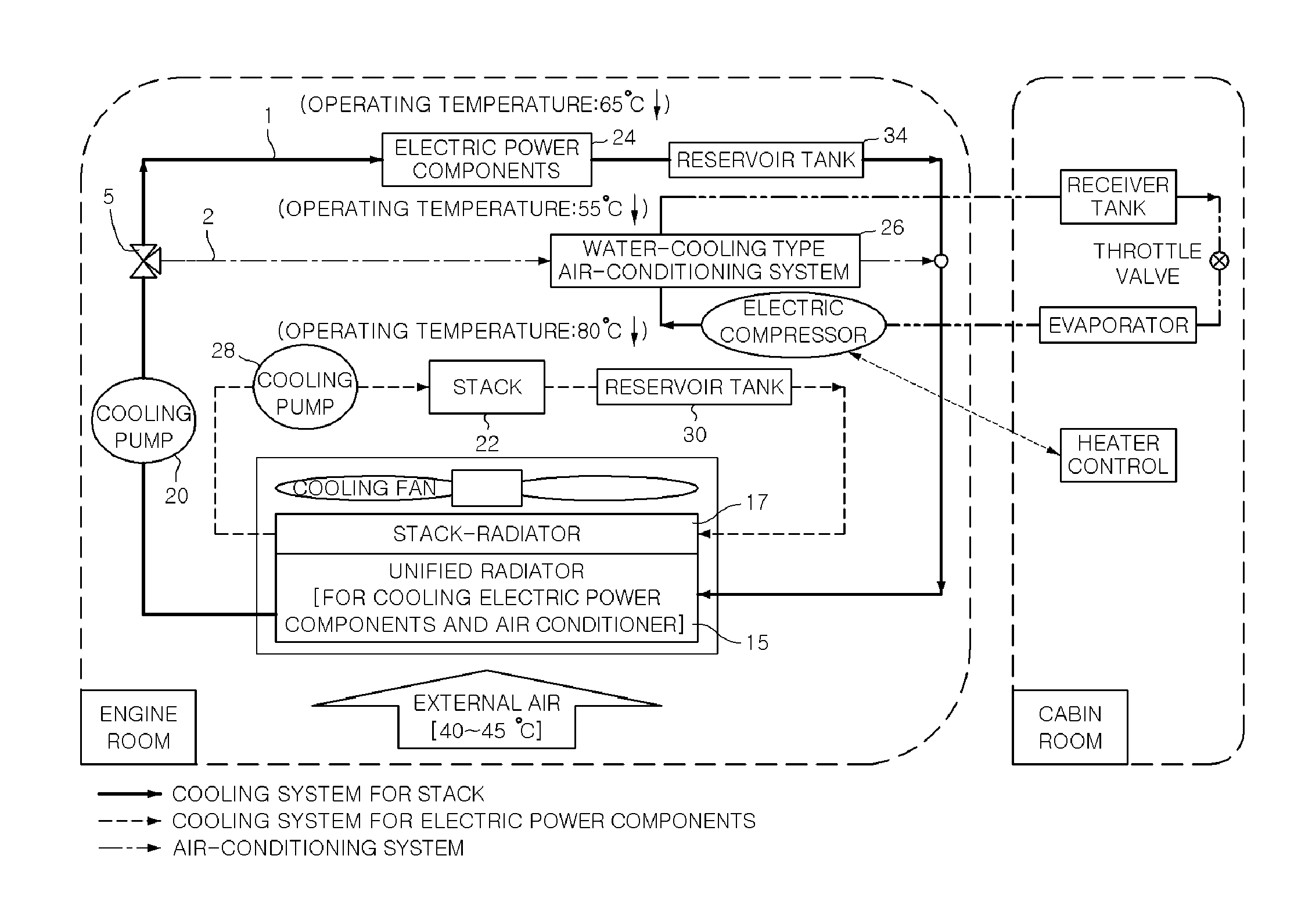
[0026]Referring to FIG. 3, the present invention includes an unified radiator 15 that cools all of working fluid flowing therethrough to cool electric power components 24 and an air-cooling type AC condenser 26 respectively, a pump 20 that is disposed in a series with the unified radiator 15 to pump up the working fluid in the unified radiator 15 to the electric power components 24 or the water-cooling type AC condenser 26, a first branch pipe 1 and a second branch pipe 2 that connect the electric power components 24 with the water-cooling type AC condenser 26 in parallel for the unified radiator 15 and the pump 20, and a valve 5 that is disposed to appropriately supply the working fluid from the pump 20 to first branch pipe 1 and second branch pipe 2.

[0027]That is, the single unified radiator 15 is formed by unifying a radiator for cooling the air-cooling type AC condenser 26 and a radiator for cooling the electric power components 24—the radiators are separate in the related art—a...

second embodiment

[0036]FIG. 4 shows the present invention, which includes an unified radiator 15 that cools all of the working fluid flowing therethrough to cool electric power components 24 and an AC condenser 26, respectively, a pump 20 that is disposed in a series with the unified radiator 15 to pump up the coolant in the unified radiator 15 to the electric power components 24 and the water-cooling type AC condenser 26, and a single coolant pipe 7 that forms a single closed circuit by connecting in a series the water-cooling type AC condenser 26 with the electric power components 24, for the unified radiator 15 and the pump 20.

[0037]That is, as compared with the parallel type first embodiment, the series type embodiment allows the working fluid passing through the unified radiator 15 to be pumped up by the pump 20 and sequentially cool the water-cooling type AC condenser 26 and the electric power components 24.

[0038]The pump 20 is positioned between the unified radiator 15 and the water-cooling t...

third embodiment

[0044]FIG. 5 shows the present invention, which includes an unified radiator 15 that cools all of the working fluid flowing therethrough to a stack 22 and an air-cooling type AC condenser 26, respectively, a pump 28 that is disposed in a series with the unified radiator 15 to pump up the coolant in the unified radiator 15 to the stack 22 or the water-cooling type AC condenser 26, a first branch pipe 1 and a second branch pipe 2 that connects the stack 22 with the water-cooling type AC condenser 26 in parallel for the unified radiator 15 and the pump 28, and a valve 5 that is disposed to appropriately supply the coolant from the pump 28 to first branch pipe 1 and second branch pipe 2.

[0045]That is, the single unified radiator 15 is formed by unifying a radiator for cooling the air-cooling type AC condenser 26 and a radiator for cooling the stack—the radiators are separated in the related art—and valve 5 is provided to appropriately supply the working fluid cooled through the unified ...


PUM


Abstract

A cooling system for an eco-friendly vehicle, may include an unified radiator that cools working fluid flowing therethrough to cool an electric power component and an air-cooling type AC condenser, respectively, a pump that is disposed in a series with the unified radiator to pump up the working fluid in the unified radiator to the electric power component or the water-cooling type AC condenser, a first branch pipe and a second branch pipe that connect the electric power components with the water-cooling type AC condenser in parallel for the unified radiator and the pump, and a valve connected to the first and second branch pipes and disposed to selectively supply the working fluid from the pump to the first branch pipe and the second branch pipe.

Description

CROSS-REFERENCE TO RELATED APPLICATIONS[0001]The present application claims priority to Korean Patent Application Number 10-2009-0119135 filed Dec. 3, 2009, the entire contents of which application is incorporated herein for all purposes by this reference.BACKGROUND OF THE INVENTION[0002]1. Field of the Invention[0003]The present invention relates to a cooling system for an eco-friendly vehicle, in more detail, a stack and electric power components of a fuel cell vehicle.[0004]2. Description of Related Art[0005]Fuel cells have the advantage of generating electricity without environmental pollution, because they produce little air pollutants and carbon dioxide, and also have higher electricity generation efficiency than thermal power generation of the related art, such that eco-friendly vehicles using a fuel cell as the power source have been increasingly developed.[0006]Hybrid vehicles can appropriately use power from a motor and an engine to drive the vehicles in accordance with tr...

Claims


Application Information

Patent Timeline
Patent Type & Authority Patents(United States)
IPC IPC(8): F28D5/00
CPCY02T10/88F01P2003/187Y02E60/50F01P2050/24H01M8/04731H01M8/04074B60H1/00278B60H2001/00307F01P3/18H01M8/04029F01P2060/14B60K2001/005F01P3/12F01P11/00
Inventor KIM, JAEYEONPARK, MANHEE
Owner HYUNDAI MOTOR CO LTD
Why Eureka
Try Eureka