
Integrated cooling system for eco-friendly vehicle

a technology for eco-friendly vehicles and cooling systems, applied in the direction of domestic cooling devices, lighting and heating devices, battery/fuel cell control arrangements, etc., can solve the problems of adverse effects on weight, parts arrangement, and manufacturing costs of vehicles, and achieve the effects of ensuring smooth and stable cooling performance, reducing ventilation resistance of radiators, and improving fuel efficiency

Active Publication Date: 2015-11-10
HYUNDAI MOTOR CO LTD +1
View PDF39 Cites 32 Cited by
  • Summary
  • Abstract
  • Description
  • Claims
  • Application Information

AI Technical Summary

Benefits of technology

The present invention is a cooling system for eco-friendly vehicles that reduces ventilation resistance, ensures smooth cooling performance, improves fuel efficiency, reduces cooling efficiency, and reduces weight of the vehicle, parts, and manufacturing cost. This is achieved without using unnecessary parts, such as a radiator, water pump, and reservoir tank. The system includes a non-repeated arrangement of heat exchangers and a reduction in the condensation pressure of the air conditioner. Overall, the invention optimizes the cooling performance of eco-friendly vehicles and increases efficiency.

Problems solved by technology

It is a problem in driving a vehicle with a motor to dissipate heat generated by the operation of the motor and heat generated by phase change of current in an inverter.
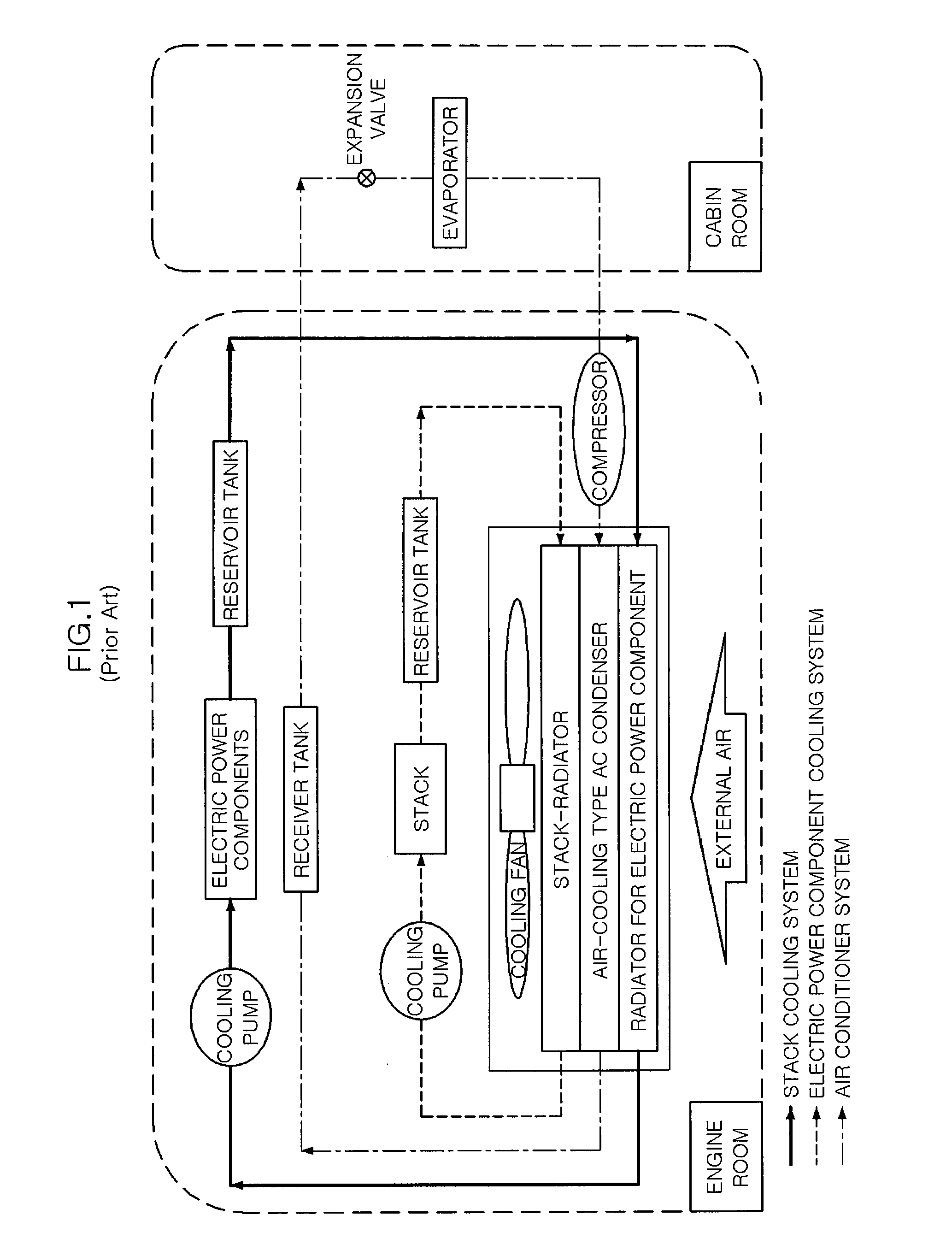
In the cooling systems in the related art, the configuration shown in FIG. 1 has difficulty in ensuring sufficient cooling performance, because the air-cooling type AC condenser increases ventilation resistance for the electric power components-radiator and the stack-radiator.
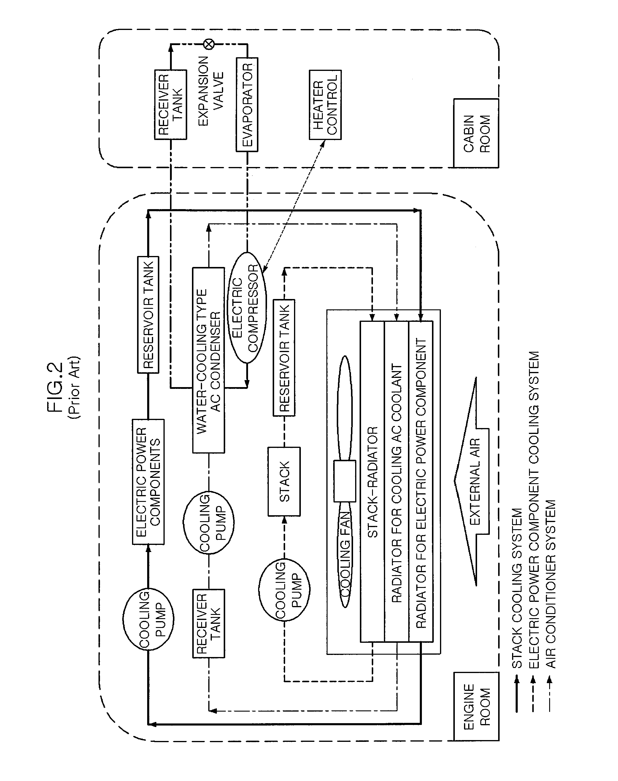
On the other hand, the configuration shown in FIG. 2 has a problem that it needs too many parts, such as a radiator, a water pump, and a reservoir, by forming cooling circuits for the stack, electric power components, and the AC condenser, decreases the cooling effect by repeatedly arranging heat exchangers, and has an adverse effect on weight, arrangement of parts, and manufacturing cost of a vehicle.

Method used


Image

  • Integrated cooling system for eco-friendly vehicle
  • Integrated cooling system for eco-friendly vehicle
  • Integrated cooling system for eco-friendly vehicle

Examples


Embodiment Construction

[0026]Reference will now be made in detail to various embodiments of the present invention(s), examples of which are illustrated in the accompanying drawings and described below. While the invention(s) will be described in conjunction with exemplary embodiments, it will be understood that present description is not intended to limit the invention(s) to those exemplary embodiments. On the contrary, the invention(s) is / are intended to cover not only the exemplary embodiments, but also various alternatives, modifications, equivalents and other embodiments, which may be included within the spirit and scope of the invention as defined by the appended claims.

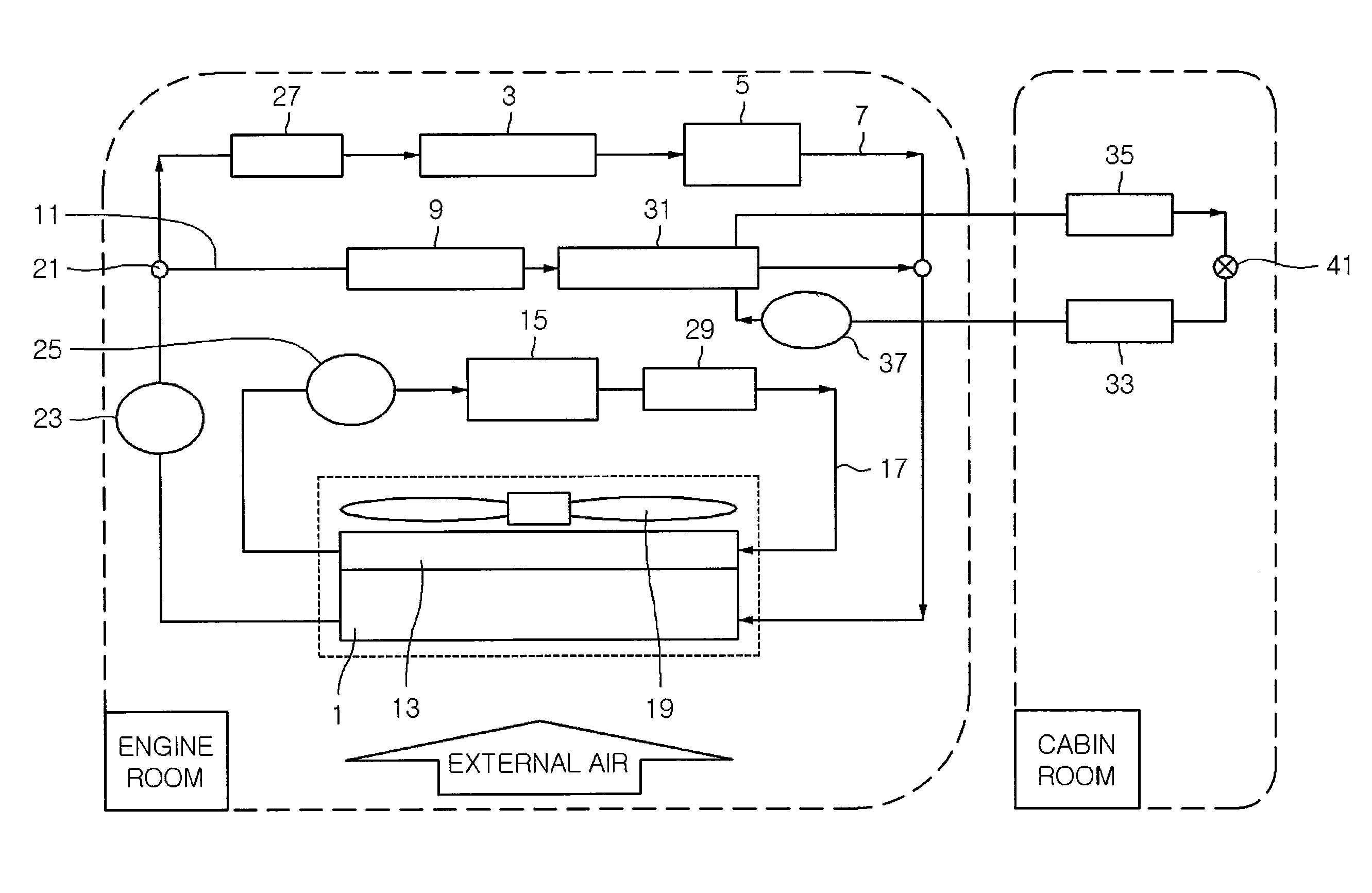
[0027]Referring to FIGS. 3 to 6, integrated cooling systems for an eco-friendly vehicle according to exemplary embodiments of the present invention include: a first radiator 1; a first cooling line 7 implementing a closed circular cooling circuit with first radiator 1 and cooling a first part 3 including some of a plurality of electri...


PUM


Abstract

The present invention makes it possible to integrate and control in one circuit the systems, such as electric power components, a driving motor, a stack, and an AC condenser which have the maximum enthalpy under similar operational temperature and use conditions, by using an integrated radiator. Therefore, it is possible to minimize air-through resistance of the radiator for cooling the stack and the electric power components and ensure smooth and stable cooling performance of the stack, electric power components, and AC condenser while improving fuel efficiency by reducing the condensation pressure of the air conditioner. Further, it is possible to improve cooling efficiency by non-repeatedly arranging heat exchangers, and reduce the weight of a vehicle, volume of the parts, and the manufacturing cost, by avoiding using too many parts, such as a radiator, a water pump, and a reservoir tank.

Description

CROSS-REFERENCE TO RELATED APPLICATIONS[0001]The present application claims priority to Korean Patent Application Numbers 10-2009-0119135 and 10-2010-0117150 filed Dec. 3, 2009 and Nov. 23, 2010, respectively, the entire contents of which are incorporated herein for all purposes by this reference.BACKGROUND OF THE INVENTION[0002]1. Field of the Invention[0003]The present invention relates to a cooling system for an eco-friendly vehicle, and more particularly, to a cooling system that cools a stack, electric power components, motors, and an air conditioner coolant in a fuel cell vehicle, or cools electric power components, motors, and an air conditioner coolant of a hybrid vehicle or an electric vehicle.[0004]2. Description of Related Art[0005]Fuel cells have the advantage of generating electricity without environmental pollution, because they produce little air pollutants and carbon dioxide, and also have higher electricity generation efficiency than thermal power generation of the ...

Claims


Application Information

Patent Timeline
Patent Type & Authority Patents(United States)
IPC IPC(8): B60H1/32B60L11/14B60H1/00B60L3/00F25D23/12F25B25/00F25B7/00B60K1/00B60L50/16
CPCB60H1/00885B60L3/0023B60L11/14B60H2001/00928B60K2001/005B60L2240/36Y02T10/70Y02T10/7077Y02T10/88B60L50/16B60L58/26B60L58/33Y02T10/7072Y02T90/40B60H1/3202B60H2001/3289B60H2001/3292F25B5/04
Inventor KIM, JAEYEONPARK, MANHEE
Owner HYUNDAI MOTOR CO LTD
Learn More