Cooler for a suspension damper

a damper and cooling device technology, applied in the direction of shock absorbers, springs/dampers, functional characteristics, etc., can solve the problems of oil contained within the damping cylinder heating up, the damping characteristics of the damping components to change, and the temperature of the oil

Active Publication Date: 2014-07-01
FOX FACTORY
View PDF13 Cites 60 Cited by
  • Summary
  • Abstract
  • Description
  • Claims
  • Application Information

AI Technical Summary

Benefits of technology

[0010]One advantage of some disclosed embodiments is that the viscous fluid in the suspension damper is continuously circulating through the cooling chamber during the stroking of the piston, thereby transferring excess heat to the air surrounding the cooling chamber. This continuous cycle helps to keep the fluid temperature at levels that will not harm the damping components.

Problems solved by technology

One disadvantage with conventional damping components is that thermal variations in operating conditions can cause the damping characteristics of the damping components to change.
Furthermore, as the damping components are subject to repetitive cycles, such as when a truck is being driven over rough terrain in the desert, the oil contained within the damping cylinder may heat up due to work performed on the oil by the damping piston.
Similarly, heat from nearby engine components may also contribute to the temperature of the oil.
At high temperatures, such as greater than 400° F., the heat can lead to a degradation of rubber sealing elements within the damping components that could cause permanent damage to the vehicle suspension as oil is no longer sealed within the damping components.

Method used


Image

  • Cooler for a suspension damper
  • Cooler for a suspension damper
  • Cooler for a suspension damper

Examples


Embodiment Construction

[0017]Integrated damper / spring vehicle shock absorbers often include a damper body surrounded by or used in conjunction with a mechanical spring or constructed in conjunction with an air spring or both. The damper often consists of a piston and shaft telescopically mounted in a fluid filled cylinder. The damping or working fluid may be, for example, hydraulic oil. A mechanical spring may be a helically wound spring that surrounds or is mounted in parallel with the damper body. As used herein, the terms “down”“up”“downward” upward”“lower”“upper” and other directional references are relative and are used for reference only.

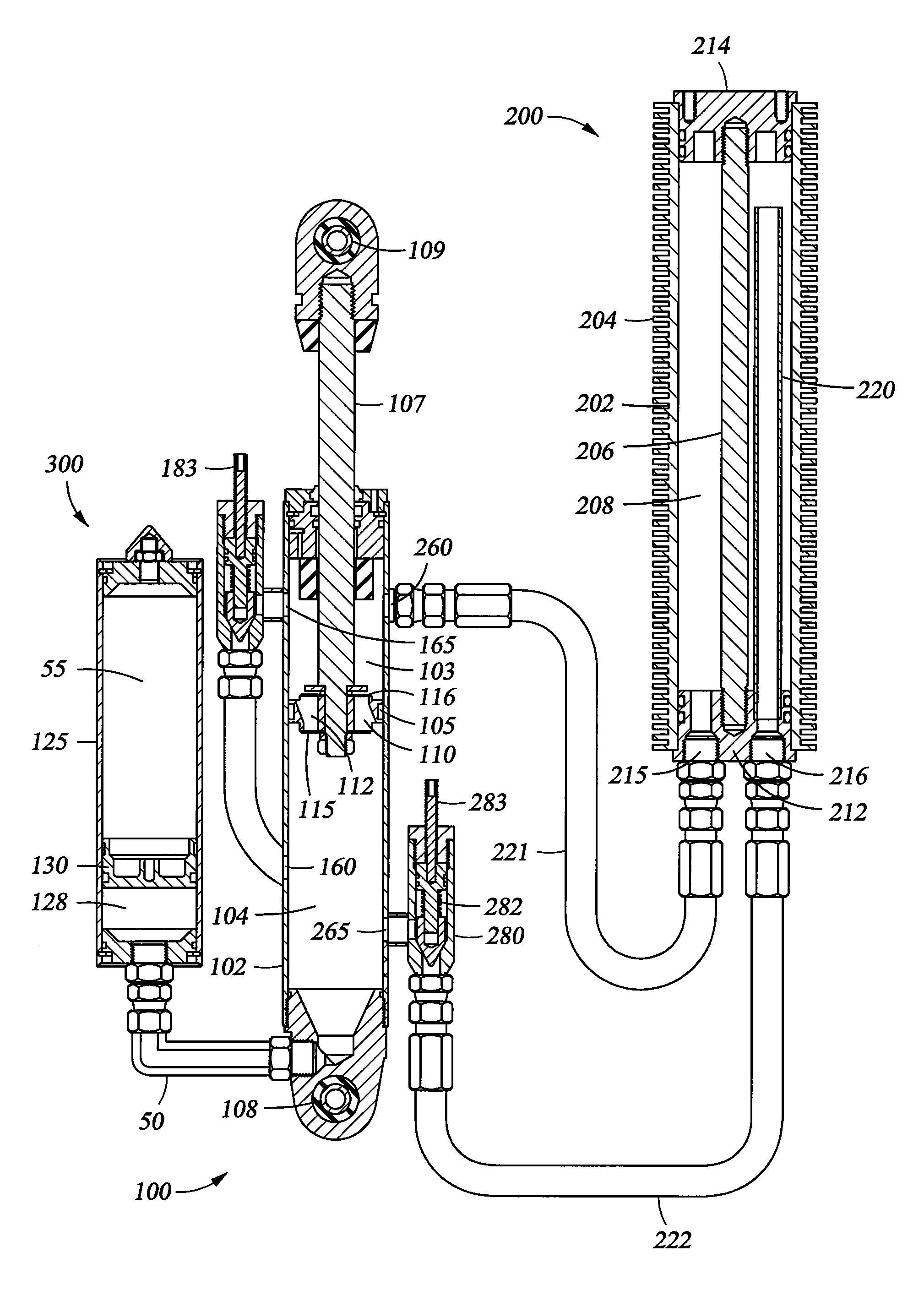
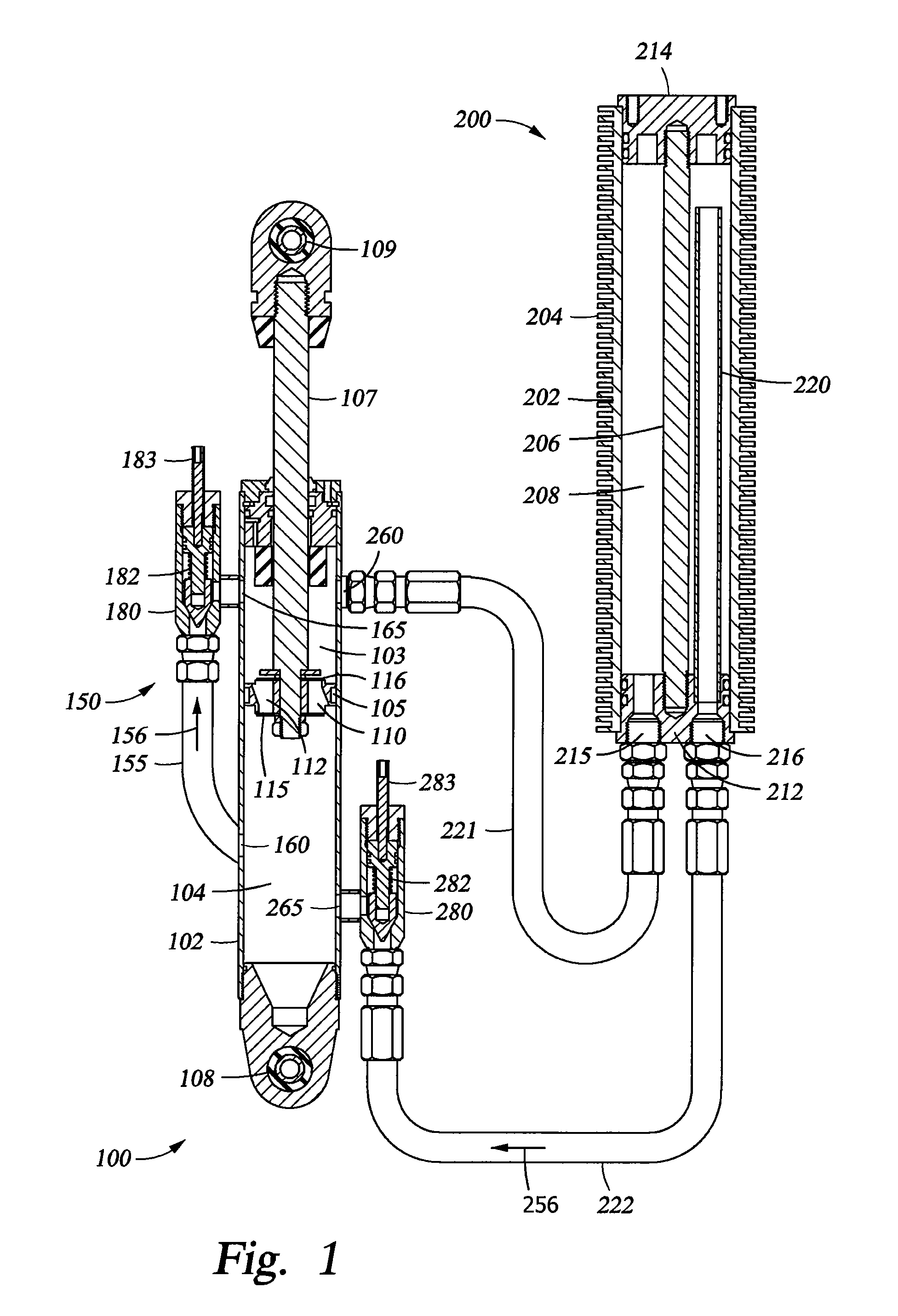
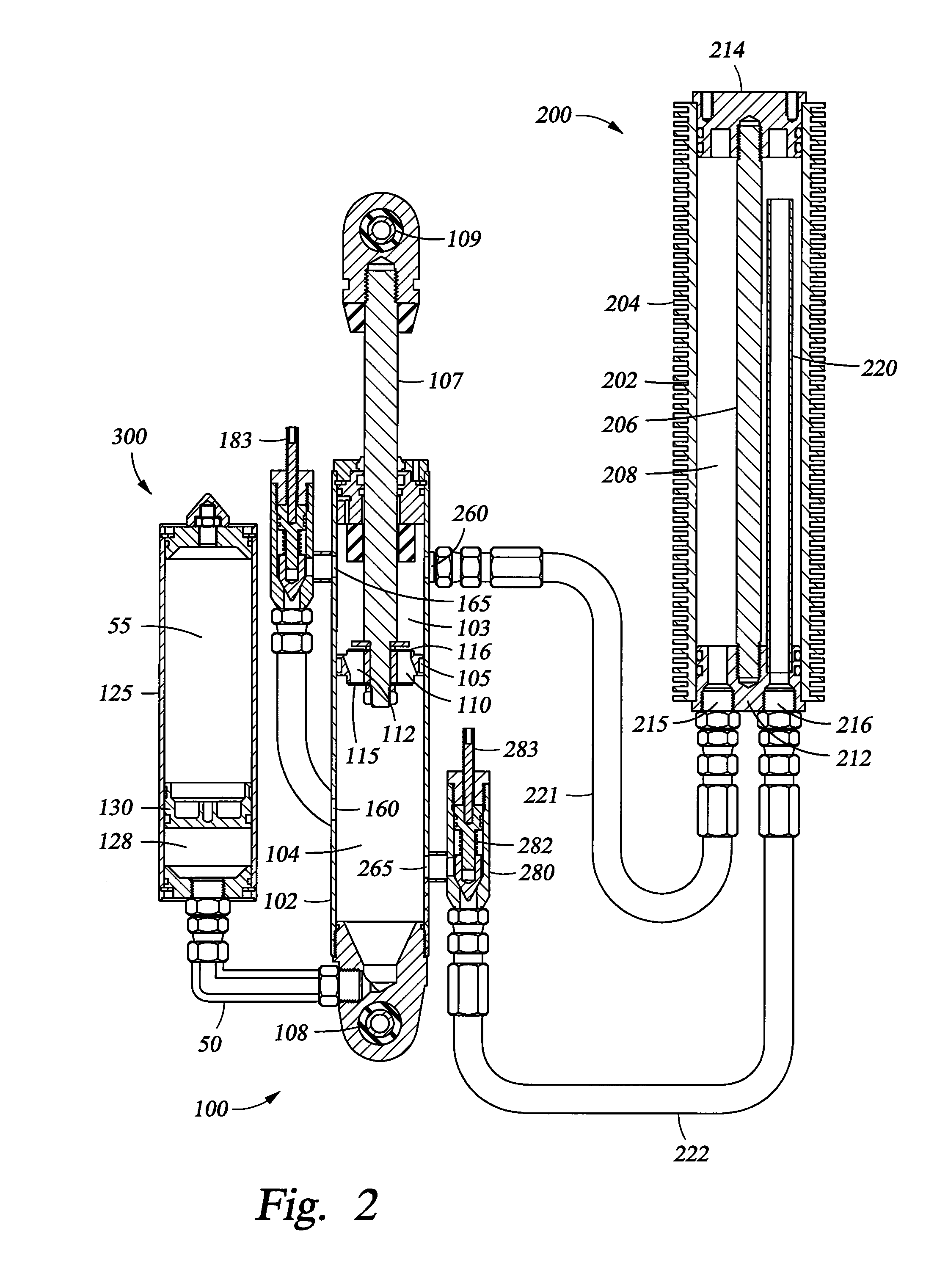
[0018]FIG. 1 is a sectional side elevation view of a suspension damping unit 100, according to one example embodiment. The damper includes a cylinder 102 with a rod 107 and a piston 105. In one embodiment, the damping fluid meters, from one side to the other side of piston 105, by passing through flow paths 110, 112 formed in the piston 105. In the embodiment shown,...


PUM


Abstract

A method and apparatus are disclosed for cooling damping fluid in a vehicle suspension damper unit. A damping unit includes a piston mounted in a fluid cylinder. A bypass fluid circuit having an integrated cooling assembly disposed therein is fluidly coupled to the fluid cylinder at axial locations that, at least at one point in the piston stroke, are located on opposite sides of the piston. The cooling assembly may include a cylinder having cooling fins thermally coupled to an exterior surface of the cylinder and made of a thermally conductive material. The bypass channel may include a check valve that permits fluid flow in only one direction through the bypass channel. The check valve may be remotely operated, either manually or automatically by an electronic controller. A vehicle suspension system may implement one or more damper units throughout the vehicle, controlled separately or collectively, automatically or manually.

Description

CROSS-REFERENCE TO RELATED APPLICATIONS[0001]This application claims benefit of U.S. Provisional Patent Application Ser. No. 61 / 449,045, filed Mar. 3, 2011, which is herein incorporated by reference in its entirety. Embodiments of this application may be used with embodiments of U.S. Provisional Patent Application Ser. No. 61 / 296,826, filed Jan. 20, 2010, U.S. patent application Ser. No. 12 / 684,072, filed Jan. 7, 2010, and U.S. patent application Ser. No. 13 / 010,697, filed Jan. 20, 2011, each of which is herein incorporated by reference in its entirety.BACKGROUND OF THE INVENTION[0002]1. Field of the Invention[0003]The invention relates generally to vehicle suspensions and, more specifically, to a cooler assembly for a suspension damper.[0004]2. Description of the Related Art[0005]Vehicle suspension systems typically include a spring component or components and a damping component or components. Typically, mechanical springs, like helical springs, are used with some type of viscous ...

Claims


Application Information

Patent Timeline
Patent Type & Authority Patents(United States)
IPC IPC(8): F16F9/42
CPCF16F9/42F16F9/464F16F9/46B60G13/08B60G17/08B60G2400/05B60G2400/106B60G2400/204B60G2400/50B60G2400/52B60G2500/10B60G2600/18B60G2800/16F16F2228/066F16F2230/18
Inventor MARKING, JOHN
Owner FOX FACTORY
Why Eureka
Try Eureka