Rotational thrombectomy wire

a thrombosis and wire technology, applied in the field of thrombosis wire, can solve the problems of high cost of multiple wire devices, long hospital procedures, and high risk of drug toxicity and bleeding complications

Inactive Publication Date: 2014-07-01
REX MEDICAL LP
View PDF313 Cites 92 Cited by
  • Summary
  • Abstract
  • Description
  • Claims
  • Application Information

AI Technical Summary

Problems solved by technology

These agents, however, are expensive, require lengthy hospital procedures and create risks of drug toxicity and bleeding complications as the clots are broken.
This multiple wire device is expensive and can be traumatic to the graft, possibly causing damage, since as the basket rotates, the graft is contacted multiple times by the spinning wires.
Other risks associated with the basket include the possibility of catching onto the graft itself and tearing the graft as well as catching and tearing the suture at the anastomotic site.
Additionally, the basket can become filled with a clot which would then require time consuming withdrawal of the basket, cleaning the basket and reinserting it into the lumen.
This device could be traumatic if used in the vessel, could denude endothelium, create vessel spasms and has the potential for basket and drive shaft fracture.
Although the sinuous wire of the '316 patent is effective in proper clinical use to macerate thrombus in dialysis grafts, it is not best suited for use in native vessels.
Clots formed in these cerebral arteries can cause stroke and in certain instances death of the patient.
Due to the size and curves of the vessels en route to the cerebral arteries from the femoral artery, as well as the size and structure of cerebral arteries themselves, access is difficult.
If the thrombectomy device is too large then navigation through the small vessels, which can be as small as 1 mm, would be difficult.
Also, if the device is too stiff, then it can damage the vessel walls during insertion.
On the other hand, if the device is too flexible, it will lack sufficient rigidity to be advanced around the vessel curves and can be caught in the vessel.

Method used


Image

  • Rotational thrombectomy wire
  • Rotational thrombectomy wire
  • Rotational thrombectomy wire

Examples


Embodiment Construction

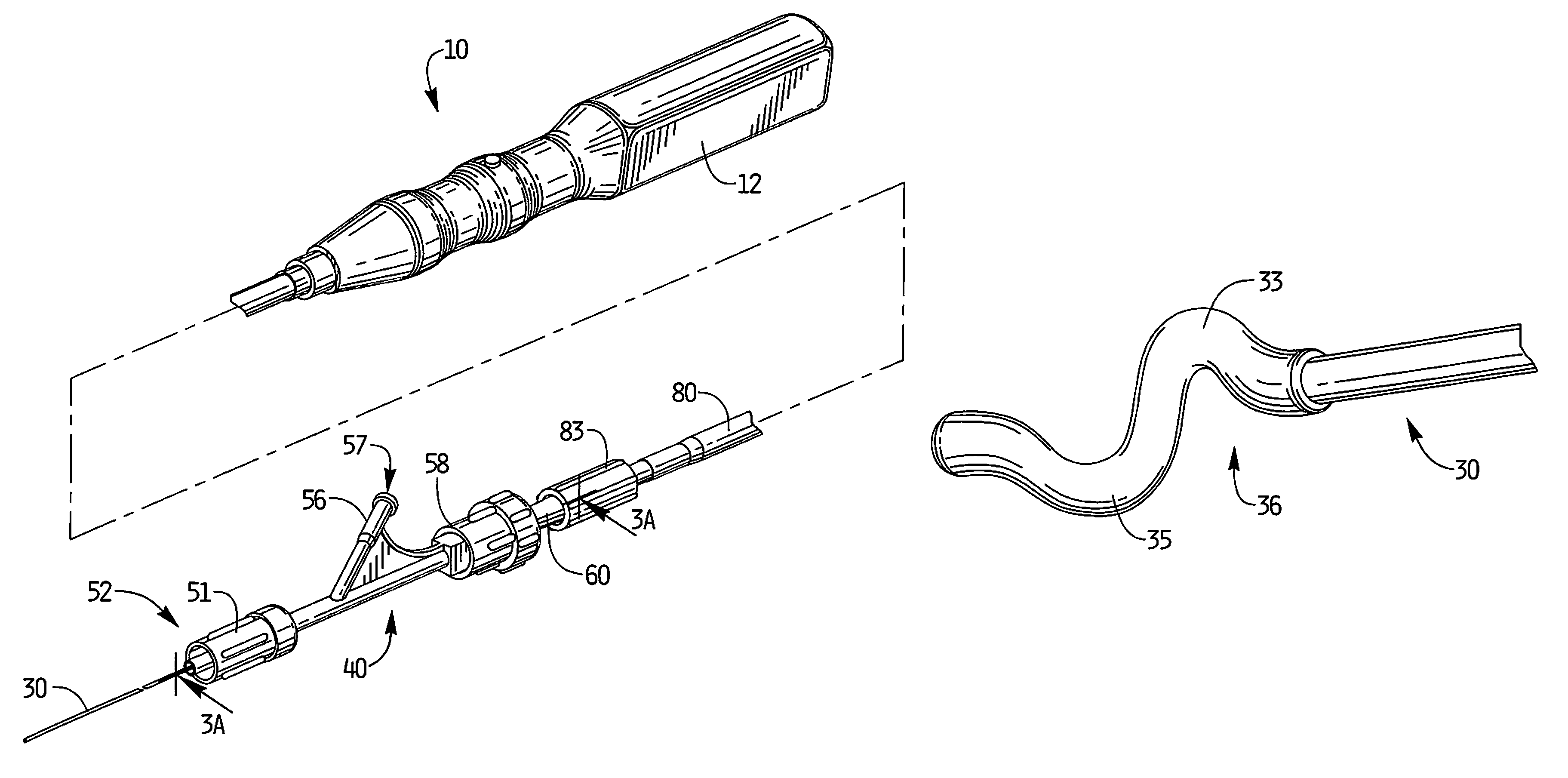
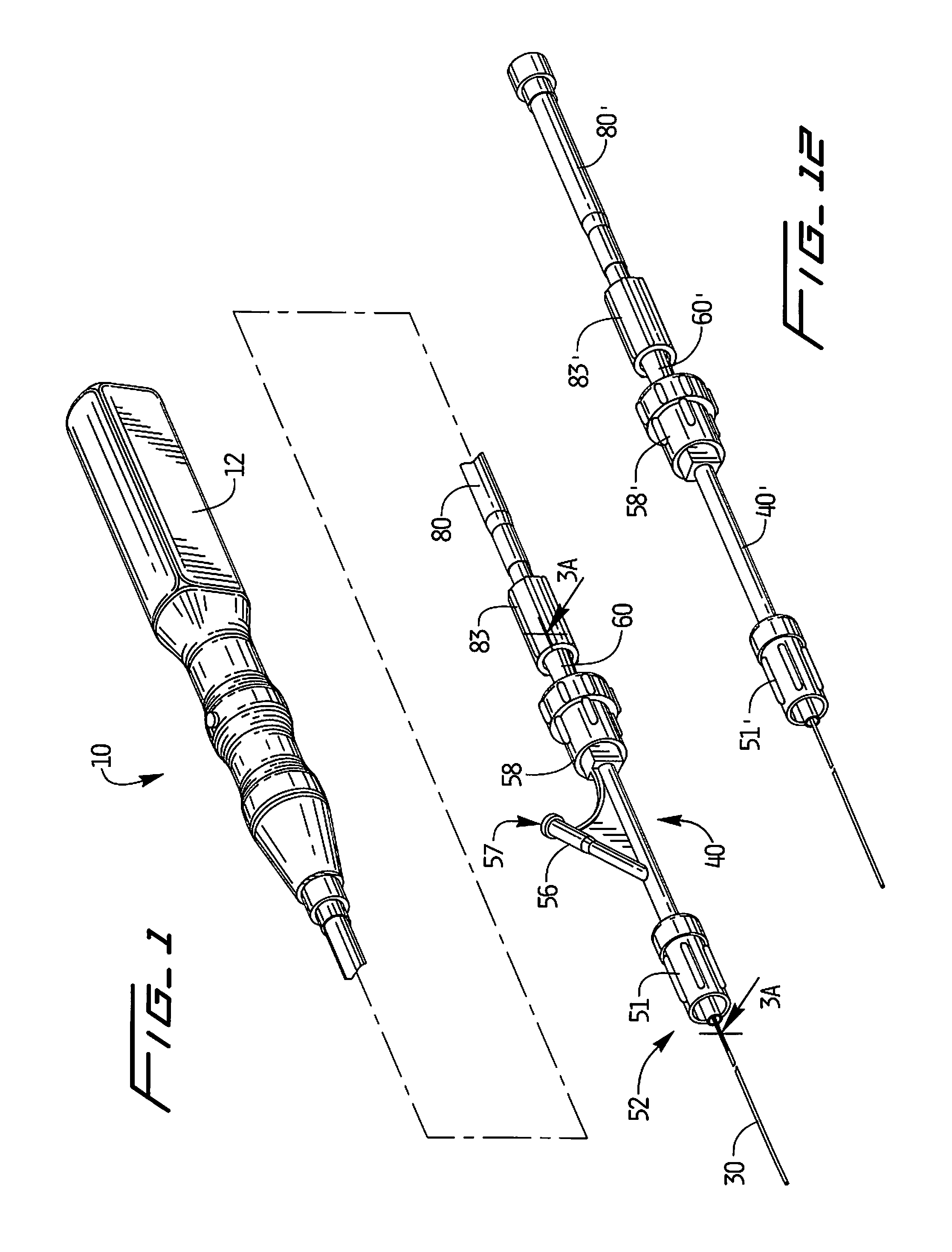
[0052]Referring now in detail to the drawings where like reference numerals identify similar or like components throughout the several views, FIG. 1 illustrates a first embodiment of the thrombectomy apparatus of the present invention.

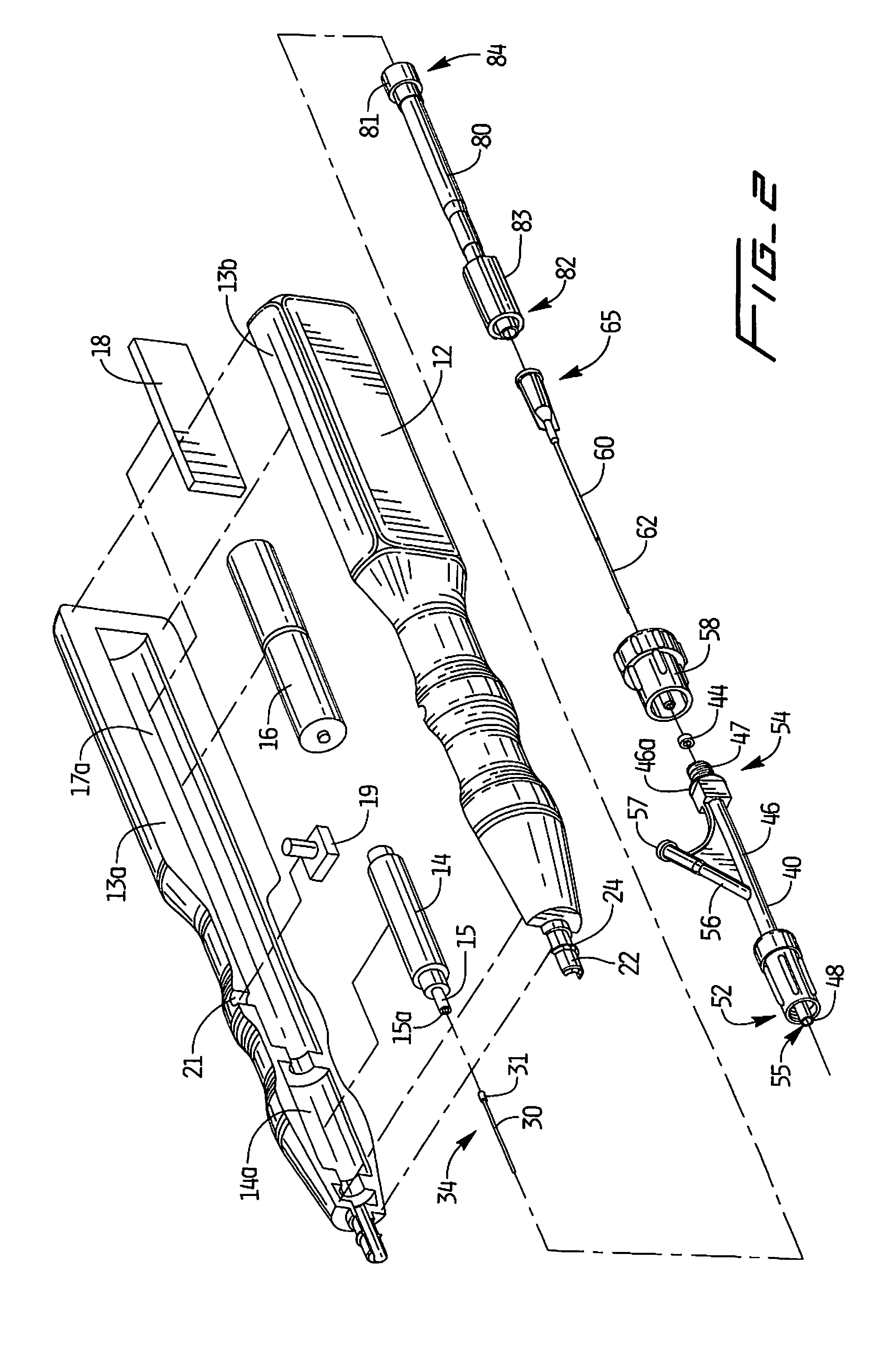
[0053]The thrombectomy apparatus of FIG. 1 is designated generally by reference numeral 10. With reference to FIGS. 1 and 2, the apparatus includes a motor housing 12, a rotational thrombectomy wire 30, a rotating hemostatic valve (RHV) 40, an introducer sheath 60 and a telescoping tube or tubular connector 80. The RHV 40 is connectable to an introducer catheter 100 discussed below in conjunction with the method of use (see e.g. FIG. 10). The introducer sheath 60 is insertable into the RHV 40 to facilitate insertion of the thrombectomy wire 30 through the RHV 40 and introducer catheter 100.

[0054]The thrombectomy apparatus or assembly 10 disclosed herein provides a rotational thrombectomy wire as a separate unit from a catheter. That is, the thrombectom...


PUM


Abstract

A rotational thrombectomy wire for breaking up vascular thrombus or other obstructive material having a core having a proximal region and a distal region and being rotatable by a motor. The distal region has a smaller diameter than the proximal region. A cable is coupled to the distal region of the core and extends distally thereof. A torque tube is positioned over the cable and a coil is positioned over a distal portion of the cable. A distal portion of the cable has a non-linear configuration. A first covering material is positioned over the coil.

Description

[0001]This application claims priority from provisional application Ser. No. 61 / 431,169, filed Jan. 10, 2011, and is a continuation in part of Ser. No. 13 / 095,329, filed Apr. 27, 2011, which claims priority from provisional application Ser. No. 61 / 334,412, filed May 13, 2010 the entire contents each of these applications are incorporated herein by reference.BACKGROUND[0002]1. Technical Field[0003]This application relates to a rotational thrombectomy wire for clearing thrombus from native vessels.[0004]2. Background of Related Art[0005]There have been various attempts to break up clots and other obstructing material in grafts or native vessels. One approach is through injection of thrombolytic agents such as urokinase or streptokinase. These agents, however, are expensive, require lengthy hospital procedures and create risks of drug toxicity and bleeding complications as the clots are broken.[0006]Other approaches to breaking up clots involve mechanical thrombectomy devices. For exam...

Claims


Application Information

Patent Timeline
Patent Type & Authority Patents(United States)
IPC IPC(8): A61B17/22
CPCA61M25/0097A61M2025/0681A61B2017/22094A61B2017/22038A61B2017/320733A61B17/320758A61B2017/00778A61B2017/320008A61B2017/320766
Inventor LEVINE, MARC-ALANLEEDLE, MICHAEL
Owner REX MEDICAL LP
Why Eureka
Try Eureka