Fuel cell system and method of controlling fuel cell system

a fuel cell and system technology, applied in the direction of fuel cells, electrochemical generators, electrical equipment, etc., can solve the problems of fuel cell deterioration, possible corrosion of carbon supports supporting catalysts of platinum or the like, etc., to suppress the deterioration, suppress the deterioration, and suppress the deterioration at the start-up

Active Publication Date: 2014-07-01
NISSAN MOTOR CO LTD
View PDF18 Cites 1 Cited by
  • Summary
  • Abstract
  • Description
  • Claims
  • Application Information

AI Technical Summary

Benefits of technology

[0009]Since the start-up frequency corresponding to a short system shutdown period tends to be high, in a range where a system shutdown period is short, it is preferable to suppress the deterioration at the start-up the degree of which depends on the start-up frequency. According to the present invention, the fuel gas can be supplied to the fuel electrode for a predetermined period after the termination of the shutdown process. Accordingly, an increase of the concentration of the oxidant gas in the fuel electrode is suppressed in the range where the system shutdown period is short. Even if the system is started up under the above condition, the deterioration at the start-up can be suppressed because the problem of so-called the hydrogen front is eased.
[0010]On the other hand, since the start-up frequency corresponding to a long system shutdown period tends to be low, in a range where the system shutdown period is long, it is preferable to suppress the deterioration during the leaving period the degree of which depends on the system shutdown period. According to the present invention, the supply of the fuel gas ends after a lapse of the predetermined period, and the fuel gas in the fuel electrode is consumed by the entering outside air. Accordingly, the presence of the fuel gas in the fuel electrode is suppressed in the range where the system shutdown period is long. Because the generation of hydrogen peroxide is suppressed under the above condition, the deterioration during the leaving period can be suppressed.
[0011]Thus, the deterioration at the start-up and the deterioration during the leaving period can be suppressed in a good balance by suppressing a larger factor causing deterioration between the deterioration at the start-up and the deterioration during the leaving period, depending on the length of the system shutdown period.

Problems solved by technology

In this case, a boundary between the air present in the fuel electrode and hydrogen newly supplied thereto, so-called a hydrogen front may deteriorate the fuel cell.
More specifically, corrosion of a carbon support supporting a catalyst of platinum or the like may possibly occur.

Method used


Image

  • Fuel cell system and method of controlling fuel cell system
  • Fuel cell system and method of controlling fuel cell system
  • Fuel cell system and method of controlling fuel cell system

Examples


first embodiment

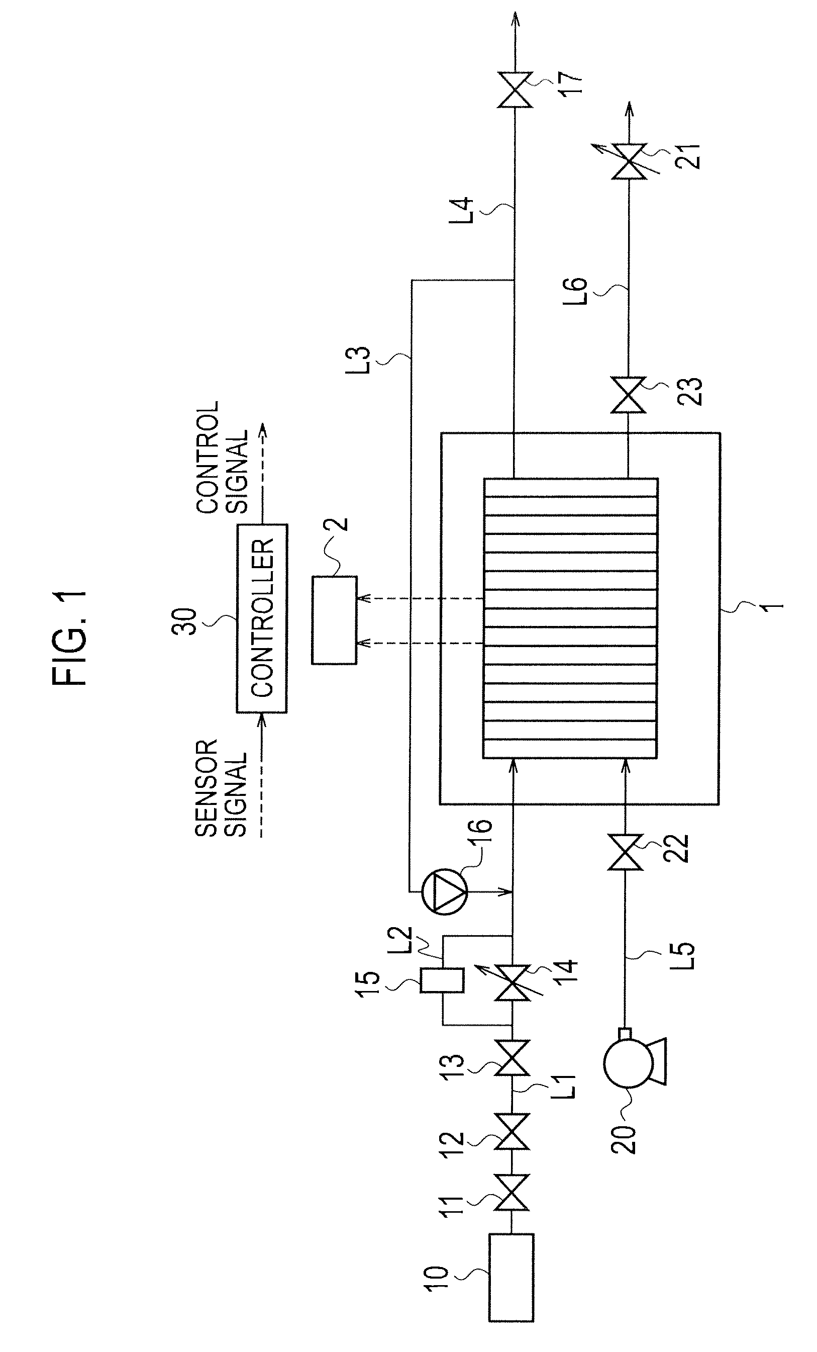
[0028]FIG. 1 is a block diagram schematically showing a configuration of a fuel cell system according to the present invention. For example, the fuel cell system is mounted on a vehicle which is a mobile unit, and the vehicle is driven by electric power supplied from the fuel cell system.

[0029]The fuel cell system includes a fuel cell stack (fuel cell) 1 formed of multiple fuel cell structures stacked on one another with separators interposed therebetween. Each fuel cell structure has a fuel electrode and an oxidant electrode facing each other with a solid polymer electrolyte membrane interposed therebetween. In the fuel cell stack 1, the fuel electrode is supplied with a fuel gas while the oxidant electrode is supplied with an oxidant gas. The fuel cell stack 1 thereby makes the fuel gas and the oxidant gas electrochemically react with each other to generate power. In this embodiment, description is given of a case where hydrogen is used as a fuel gas and the air is used as an oxid...

second embodiment

[0081](Second Embodiment)

[0082]FIG. 8 is a block diagram schematically showing the configuration of a fuel cell system according to a second embodiment. The fuel cell system according to the second embodiment is different from that of the first embodiment in that the system includes buffer means for holding medium pressure hydrogen. Note that, the configuration that overlaps with that of the first embodiment is omitted while the reference numeral of the overlapping configuration is cited, and description is given mainly of differences below.

[0083]The medium pressure hydrogen valve 13 shown in the first embodiment is omitted in the hydrogen system of this embodiment. In other words, in this embodiment, the tank main valve 11 serves as the medium pressure hydrogen valve 13 shown in the first embodiment. Further, a tank 19 (buffer means) which includes a capacity part reserving hydrogen is connected to the bypass passage L2 through a connection passage L7. An open / close valve 18 which ...


PUM

PropertyMeasurementUnit
electric poweraaaaaaaaaa
flow rateaaaaaaaaaa
areaaaaaaaaaaa

Abstract

Deterioration at the start-up and deterioration during the leaving period are suppressed in a good balance. As a system shutdown process, a controller (30) causes consumption of the air (oxygen) present in an oxidant electrode of a fuel cell stack (1) (oxygen consumption control). Further, after the termination of the oxygen consumption control, the controller (30) performs control to set a medium pressure hydrogen valve (13) and a hydrogen pressure adjustment valve (14) in a closed state. The controller (30) thereby causes hydrogen to be held in a passage located between the medium pressure hydrogen valve (13) and the hydrogen pressure adjustment valve (14). During a system shutdown period, a predetermined amount of hydrogen (medium pressure hydrogen) held in the hydrogen supply passage (L1) at a position between the medium pressure hydrogen valve (13) and the hydrogen pressure adjustment valve (14) can be supplied to the fuel electrode of the fuel cell stack (1) through a bypass passage (L2).

Description

[0001]The present application is a National Stage Entry of International Application PCT / JP2009 / 060831, filed on Jun. 15, 2009, the disclosure of which is incorporated by reference herein in its entirety.TECHNICAL FIELD[0002]The present invention relates to a fuel cell system and a method of controlling the fuel cell system.BACKGROUND ART[0003]Heretofore, a fuel cell is known which generates power by making a fuel gas (hydrogen, for example) supplied to a fuel electrode and an oxidant gas (the air, for example) supplied to an oxidant electrode electrochemically react with each other. In a fuel cell system including the fuel cell, the air is sometimes present in both the oxidant electrode and the fuel electrode at a start-up. In this case, a boundary between the air present in the fuel electrode and hydrogen newly supplied thereto, so-called a hydrogen front may deteriorate the fuel cell. More specifically, corrosion of a carbon support supporting a catalyst of platinum or the like m...

Claims


Application Information

Patent Timeline
Patent Type & Authority Patents(United States)
IPC IPC(8): H01M8/04
CPCH01M8/04753H01M8/04089Y02E60/50H01M8/04589H01M8/04223H01M8/04303H01M8/04228
Inventor KUMADA, MITSUNORISHIMOI, RYOICHICHIKUGO, HAYATOAOYAMA, TAKASHI
Owner NISSAN MOTOR CO LTD
Why Eureka
Try Eureka