
Dry etch process

a technology of dry etching and process, which is applied in the direction of electrical equipment, basic electric elements, electric discharge tubes, etc., can solve the problems of less dry etching processes that can evenly and selectively remove metals

Inactive Publication Date: 2014-07-01
APPLIED MATERIALS INC
View PDF674 Cites 176 Cited by
  • Summary
  • Abstract
  • Description
  • Claims
  • Application Information

AI Technical Summary

Benefits of technology

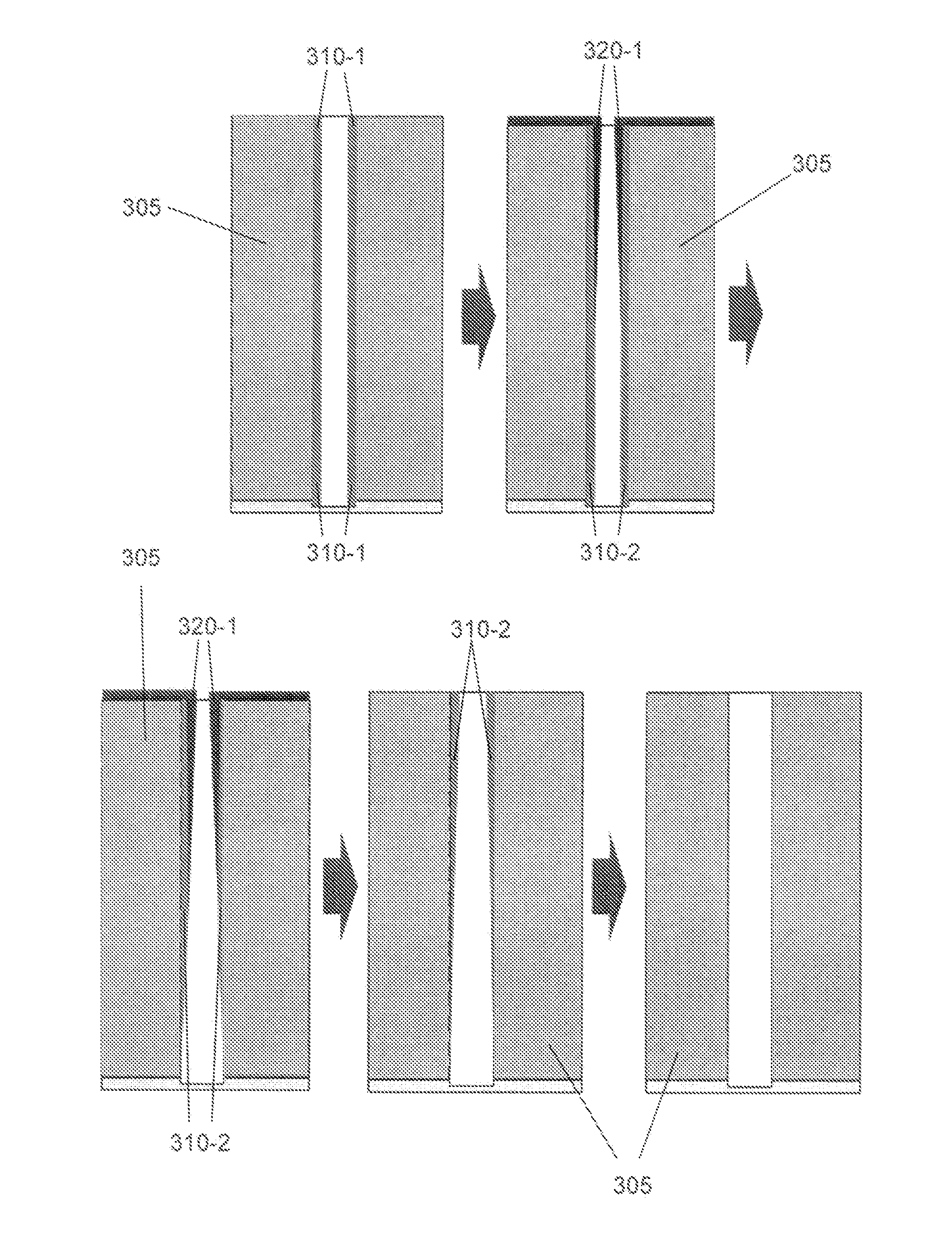
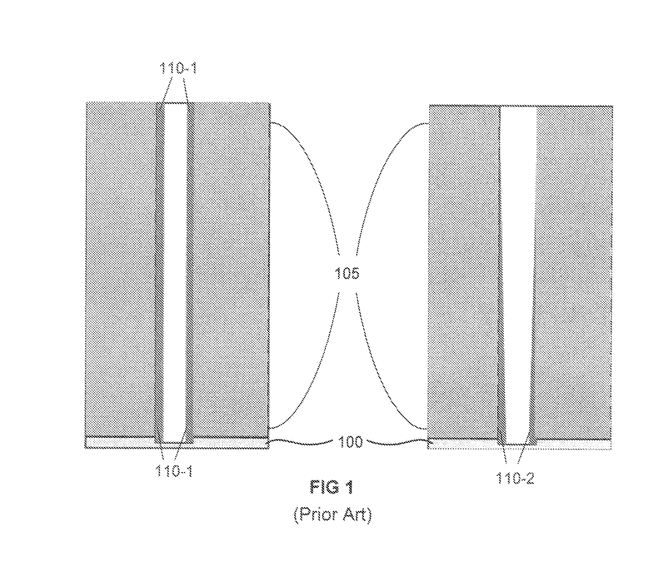
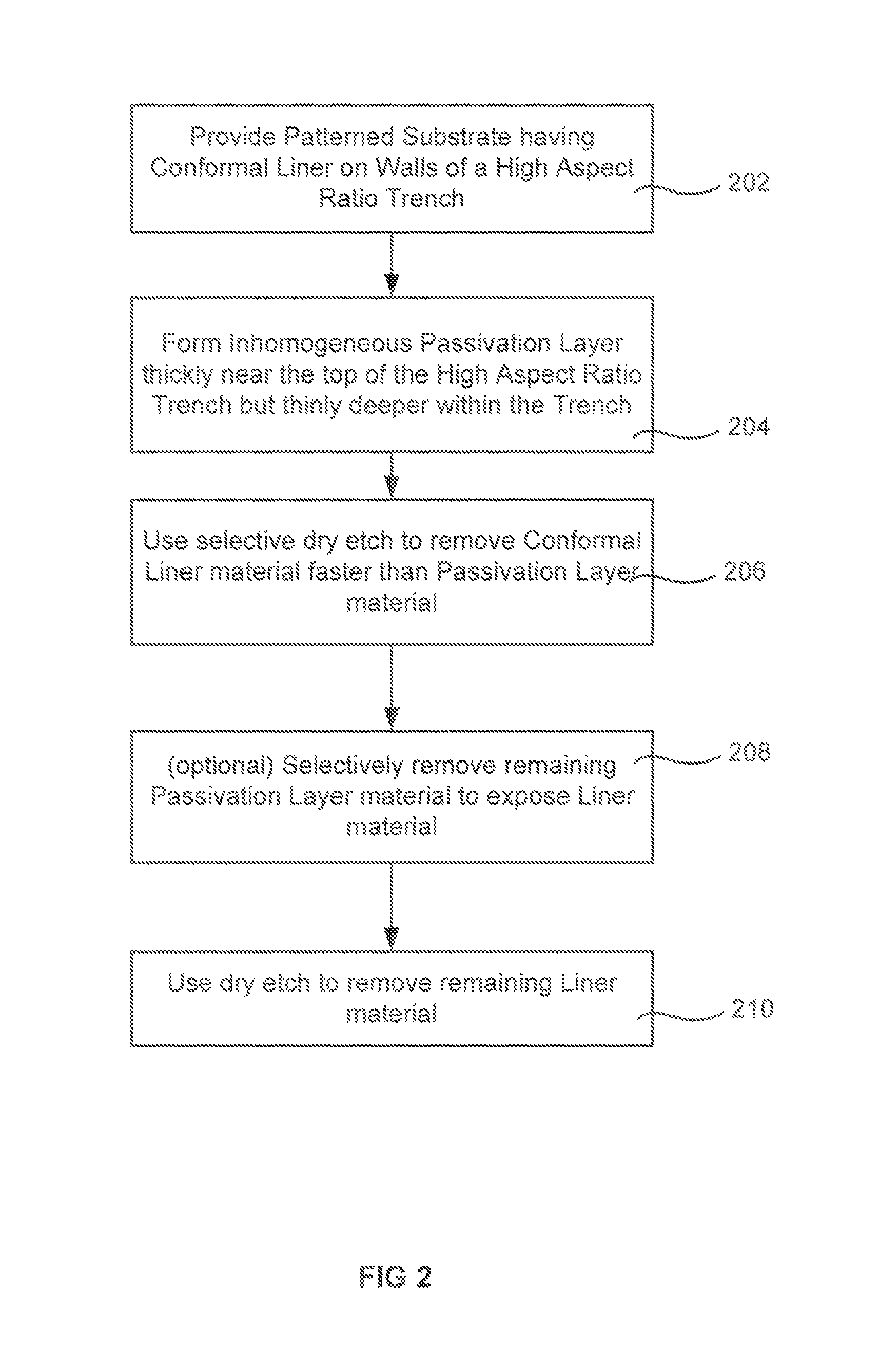
[0005]A method for conformal dry etch of a liner material in a high aspect ration trench is achieved by depositing or forming an inhomogeneous passivation layer which is thicker near the opening of a trench but thinner deep within the trench. The methods described herein use a selective etch following formation of the inhomogeneous passivation layer. The selective etch etches liner material faster than the passivation material. The inhomogeneous passivation layer suppresses the etch rate of the selective etch near the top of the trench (where it would otherwise be fastest) and gives the etch a head start deeper in the trench (where it would otherwise be slowest). This method may also find utility in removing bulk material uniformly from within a trench.

Problems solved by technology

However, fewer dry-etch processes have been developed to evenly and selectively remove metals and / or their oxidation.

Method used


Image

  • Dry etch process
  • Dry etch process
  • Dry etch process

Examples


Embodiment Construction

[0016]A method for conformal dry etch of a liner material in a high aspect ratio trench is achieved by depositing or forming an inhomogeneous passivation layer which is thicker near the opening of a trench but thinner deep within the trench. The methods described herein use a selective etch following formation of the inhomogeneous passivation layer. The selective etch etches liner material faster than the passivation material. The inhomogeneous passivation layer suppresses the etch rate of the selective etch near the top of the trench (where it would otherwise be fastest) and gives the etch a head start deeper in the trench (where it would otherwise be slowest). This method may also find utility in removing bulk material uniformly from within a trench.

[0017]During gas phase etch processes, etchant precursors have been found to lose some effectiveness progressively as they diffuse deeper within a high aspect ratio trench. This results from the increased number of collisions which occ...


PUM


Abstract

A method for conformal dry etch of a liner material in a high aspect ratio trench is achieved by depositing or forming an inhomogeneous passivation layer which is thicker near the opening of a trench but thinner deep within the trench. The method described herein use a selective etch following formation of the inhomogeneous passivation layer. The selective etch etches liner material faster than the passivation material. The inhomogeneous passivation layer suppresses the etch rate of the selective etch near the top of the trench (where it would otherwise be fastest) and gives the etch a head start deeper in the trench (where is would otherwise be slowest). This method may also find utility in removing bulk material uniformly from within a trench.

Description

CROSS-REFERENCE TO RELATED APPLICATIONS[0001]This application claims the benefit of U.S. Provisional Application No. 61 / 724,767 by Zhang et al, filed Nov. 9, 2012, and titled “DRY ETCH PROCESS.” This application also claims the benefit of U.S. Provisional Application No. 61 / 732,074 by Kim et al, filed Nov. 30, 2012 and titled “DRY-ETCH FOR SELECTIVE OXIDATION REMOVAL.” Each of the above U.S. Provisional Applications is incorporated herein in its entirety for all purposes.BACKGROUND OF THE INVENTION[0002]Integrated circuits are made possible by processes which produce intricately patterned material layers on substrate surfaces. Producing patterned material on a substrate requires controlled methods for removal of exposed material. Chemical etching is used for a variety of purposes including transferring a pattern in photoresist into underlying layer, thinning layers or thinning lateral dimensions of features already present on the surface. Often it is desirable to have an etch proces...

Claims


Application Information

Patent Timeline
Patent Type & Authority Patents(United States)
IPC IPC(8): H01L21/76
CPCH01L21/31122H01L21/3065H01L21/31116H01J2237/3347H01L21/32136H01L21/32137H01J37/32357
Inventor ZHANG, JINGCHUNINGLE, NITIN K.WANG, ANCHUAN
Owner APPLIED MATERIALS INC
Learn More