Flexural vibrating reed, flexural vibrator, and piezoelectric device

a flexural vibrating reed and flexural vibrating technology, which is applied in the direction of oscillation generators, solid-state devices, generators/motors, etc., can solve the problems of reducing the q value of the flexural vibrating reed, affecting the flexural vibration, etc., to prevent the reduction of the q value, and significantly degrade the flexural vibration portion.

Inactive Publication Date: 2014-07-01
SEIKO EPSON CORP
View PDF26 Cites 5 Cited by
  • Summary
  • Abstract
  • Description
  • Claims
  • Application Information

AI Technical Summary

Benefits of technology

[0012]According to Applications 1 to 3, since the first depth of the first groove and the second depth of the second groove are smaller than the distance between the surface including the third surface and the surface including the fourth surface, the first and second grooves do not penetrate between the surface including the third surface and the surface including the fourth surface. Therefore, compared to a case where a through-hole is provided in a flexural vibrating portion, rigidity of the flexural vibrating portion can be improved. In addition, since the sum of the first depth of the first groove and the second depth of the second groove are greater than the distance, a heat transfer path between a first expandable portion (the first surface) and a second expandable portion (the second surface) cannot be formed as a straight line. As such, the heat transfer path between the first expandable portion (the first surface) and the second expandable portion (the second surface) can be made to detour to the first and second grooves and thus be lengthened. Therefore, a relaxation time for temperature equilibrium by thermal conduction (heat transfer) is lengthened, so that a relaxation vibration frequency which is in inverse proportion to the relaxation time becomes distant from a flexural vibration frequency. Accordingly, fluctuation of the Q value caused by the thermoelastic effect is suppressed, thereby realizing a reduction in the size of the flexural vibrating reed.
[0014]Accordingly, since the first and second grooves are disposed to intersect the geodesic line establishing the shortest distance between the surface including the first surface and the surface including the second surface, the heat transfer path between the first and second surfaces can be made to detour to the first and second grooves and thus be longer than the shortest distance between the surface including the first surface and the surface including the second surface. Therefore, fluctuation of the Q value caused by the thermoelastic effect is suppressed, thereby realizing a reduction in the size of the flexural vibrating reed.
[0018]Accordingly, the relaxation vibration frequency becomes sufficiently distant from the flexural vibration frequency, so that a reduction in the Q value due to the thermoelastic effect is suppressed, thereby realizing a reduction in the size of the flexural vibrating reed.
[0020]Accordingly, since the first and second grooves are disposed on the base side from the half of the length in the extension direction of the flexural vibrating portion from the base, where transfer of heat relatively significantly occurs due to the flexural vibration, the effects described above can be exhibited. In addition, mechanical strength of a part over the half of the length in the extension direction of the flexural vibrating portion from the base, where transfer of heat due to the flexural vibration relatively insignificantly occurs, can be ensured.

Problems solved by technology

Typically, it is known that as a flexural vibrating reed is reduced in size, the Q value is reduced, and thus flexural vibration is impeded.
In another opinion, energy lost due to thermal conduction cannot be used as the flexural vibration energy, resulting in a reduction in the Q value of the flexural vibrating reed.

Method used


Image

  • Flexural vibrating reed, flexural vibrator, and piezoelectric device
  • Flexural vibrating reed, flexural vibrator, and piezoelectric device
  • Flexural vibrating reed, flexural vibrator, and piezoelectric device

Examples


first embodiment

[0044]Hereinafter, a first embodiment will be described with reference to FIGS. 1 to 4.

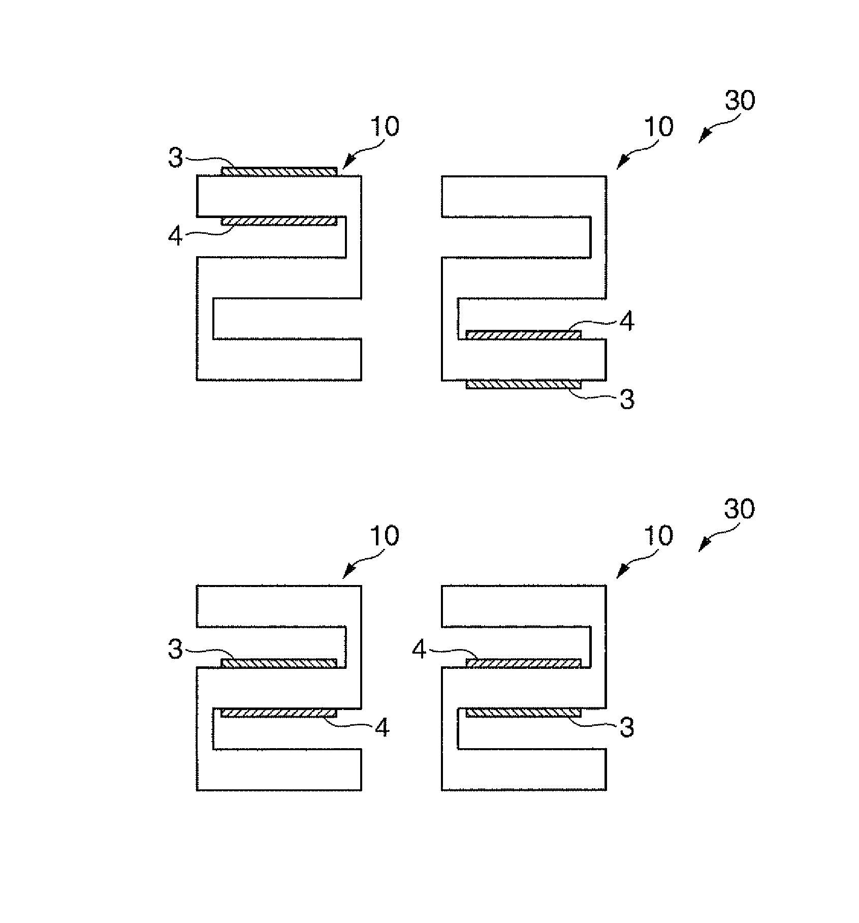
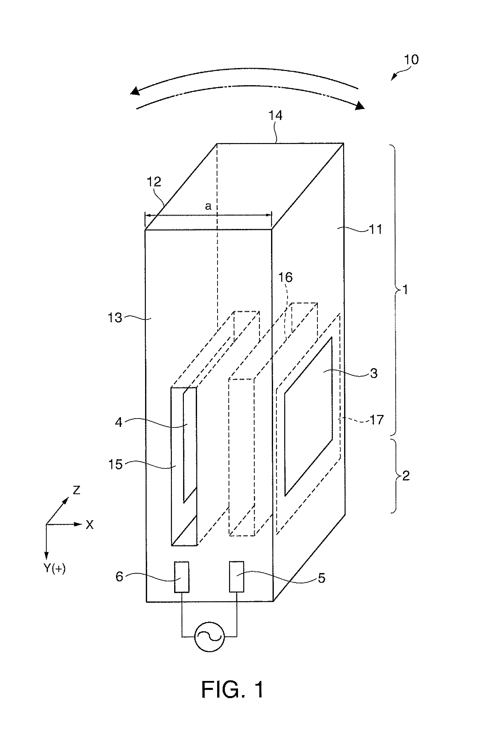
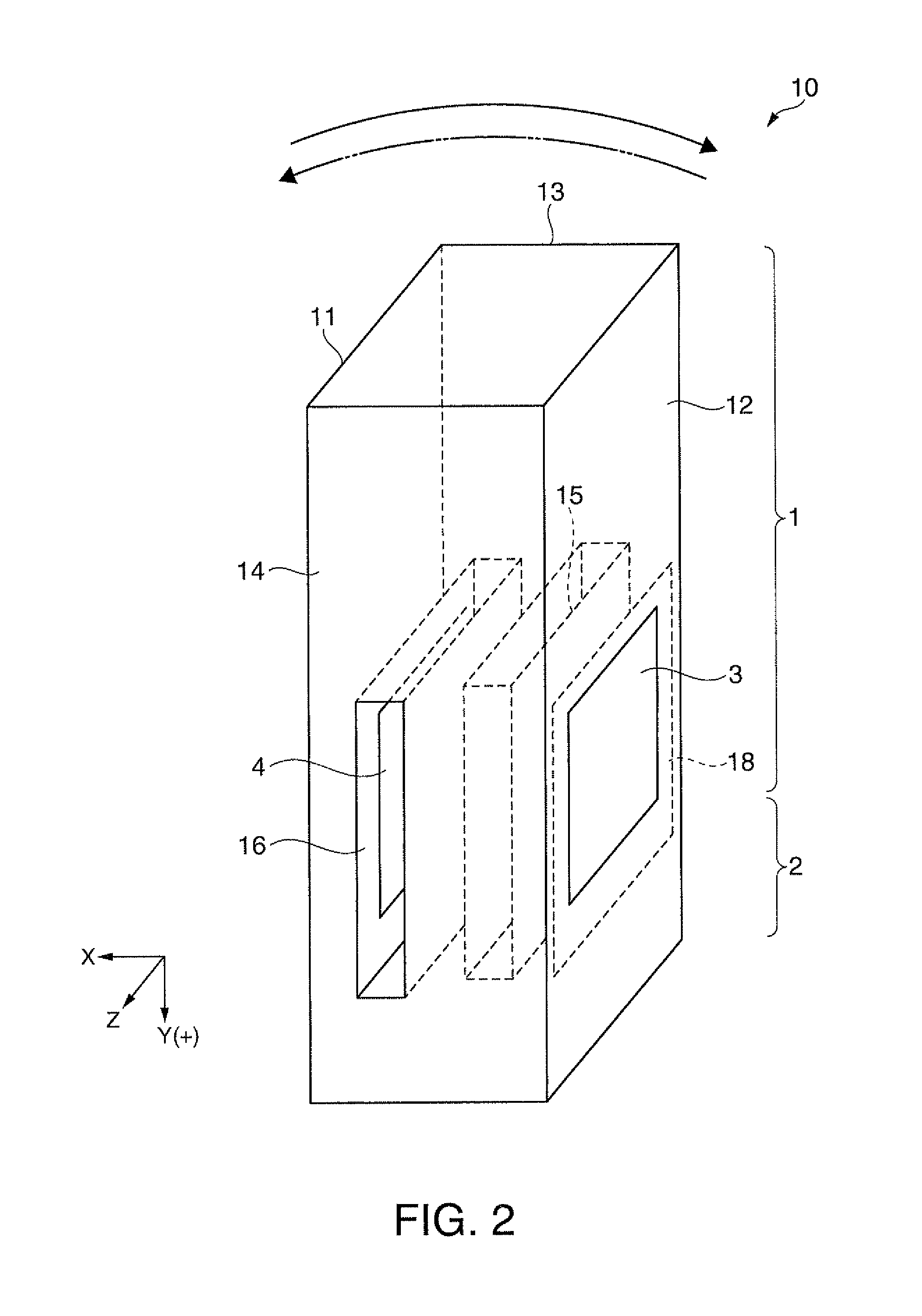
[0045]FIG. 1 is a schematic perspective view illustrating a crystal vibrating reed 10 according to the first embodiment. FIG. 2 is a schematic perspective view illustrating the crystal vibrating reed 10 illustrated in FIG. 1 as seen from a direction rotated by 180° about the Y axis. FIG. 3 is a Z-X schematic cross-sectional view as seen from the Y(+) direction of FIGS. 1 and 2 and is a schematic wiring diagram. FIG. 4 is a graph showing Q dependency of flexural vibrating reeds (crystal vibrating reed) on f / fm and is a graph showing a comparison in cross-sectional shapes of flexural vibrating portions.

[0046]As illustrated in FIGS. 1 and 2, the crystal vibrating reed 10 includes a flexural vibrating portion 1 which is a vibrating portion, a base 2, excitation electrodes 3 and 4, and fixed electrodes 5 and 6. The crystal vibrating reed 10 includes a first surface 11 which is a third principal surface...

second embodiment

[0076]Hereinafter, a second embodiment will be described with reference to FIGS. 5 to 7.

[0077]FIG. 5 is a schematic perspective view illustrating a crystal vibrating reed 20 according to a second embodiment. FIGS. 6 and 7 are Z-X schematic cross-sectional views as seen from the Y(+) direction of FIG. 5, and are schematic wiring diagrams.

[0078]The crystal vibrating reed 20 illustrated in FIG. 5 includes two crystal vibrating reeds 10 of the first embodiment illustrated in FIGS. 1 and 2. Accordingly, like elements are denoted by like reference numerals, and description of the configuration will be omitted. Here, the shapes and arrangement illustrated in FIG. 3(a) are exemplified for the description of the flexural vibrating portion 1 which is the vibrating portion, the excitation electrodes 3 and 4, and the base 2.

[0079]As illustrated in FIG. 5, the crystal vibrating reed 20 includes two crystal vibrating reeds 10 each including the flexural vibrating portion 1 which is the vibrating ...

modified example 1

[0083]FIG. 6(b) illustrates a modified example of the second embodiment related to the first and second grooves and 16 illustrated in FIG. 6(a). FIG. 6(b) is different from FIG. 6(a) in the arrangement of the first and second grooves 15 and 16 of the other flexural vibrating portion 1 illustrated on the right in FIG. 6(b). That is, the first groove 15 provided in the third surface 13 which is the first principal surface is disposed to oppose the first surface 11, and the second groove 16 provided in the fourth surface 14 which is the second principal surface is disposed to oppose the second surface 12.

[0084]The arrangement and wiring of the one flexural vibrating portion 1, the base 2, and the two pairs of the excitation electrodes 3 and 4 illustrated on the left are as illustrated in FIG. 6(a). In addition, as in FIG. 6(a), an alternating current flows between the excitation electrodes 3 and 4. Accordingly, in the flexural vibrating portion 1, flexural vibration indicated by the so...


PUM


Abstract

Deterioration of the Q value caused by the thermoelastic effect is suppressed. Since a first depth of a first groove and a second depth of a second groove are smaller than a distance between a surface including a third surface and a surface including a fourth surface, the first and second grooves do not penetrate between the surface including the third surface and the surface including the fourth surface. In addition, the sum of the first depth of the first groove and the second depth of the second groove is greater than the distance between the third and fourth surfaces, a heat transfer path between a first expandable portion (the first surface) and a second expandable portion (the second surface) cannot be formed as a straight line. As such, the heat transfer path between the first expandable portion (the first surface) and a second expandable portion (the second surface) is made to detour to the first and second grooves and and thus be lengthened.

Description

TECHNICAL FIELD[0001]The present invention relates to a flexural vibrating reed, a flexural vibrator, and a piezoelectric device.BACKGROUND ART[0002]Typically, it is known that as a flexural vibrating reed is reduced in size, the Q value is reduced, and thus flexural vibration is impeded. This is due to the thermoelastic effect that occurs as relaxation oscillation that is in inverse proportion to the relaxation time for temperature equilibrium by transfer of heat and a vibration frequency of the flexural vibrating reed become closer. As flexural vibration occurs in the flexural vibrating reed, elastic deformation occurs, and thus the temperature of a contracting surface is increased and the temperature of an expanding surface is reduced, resulting in a temperature difference inside the flexural vibrating reed. The flexural vibration is impeded by the relaxation oscillation that is in inverse proportion to the relaxation time for the temperature equilibrium from the temperature diff...

Claims


Application Information

Patent Timeline
Patent Type & Authority Patents(United States)
IPC IPC(8): H03H9/21H01L41/22H01L41/23H01L41/311H01L41/332
CPCH03H9/21H03H9/0547H03H9/1021H03H9/19H03H9/215H01L2224/48091H01L2224/48227H01L2924/00014H10N30/20H03B5/32
Inventor FURUHATA, MAKOTOFUNAKAWA, TAKEOYAMAZAKI, TAKASHI
Owner SEIKO EPSON CORP
Why Eureka
Try Eureka