Electron beam exit window in electron beam emitter and method for forming the same

a technology of electron beam and exit window, which is applied in the direction of instruments, paper/cardboard containers, therapy, etc., can solve the problems of reducing the ability of the support plate to dissipate heat from the exit window foil, and achieve the effects of reducing beam interception, reducing thermal expansion stretching or gathering of the exit window foil, and facilitating heat conductivity

Active Publication Date: 2014-07-01
HITACHI ZOSEN CORP
View PDF7 Cites 0 Cited by
  • Summary
  • Abstract
  • Description
  • Claims
  • Application Information

AI Technical Summary

Benefits of technology

[0003]The present invention can provide an exit window including an exit window foil, and a support grid contacting and supporting the exit window foil, in which the exit window foil can operate at lower temperatures than in the prior art. The support grid can have first and second grids, each having respective first and second grid portions that are positioned in alignment and thermally isolated from each other. The first and second grid portions can each have a series of apertures that are aligned for allowing the passage of a beam therethrough to reach and pass through the exit window foil. The second grid portion can contact the exit window foil. The first grid portion can mask the second grid portion and the exit window foil from heat caused by the beam striking the first grid portion.
[0004]In particular embodiments, the exit window can be in an electron beam emitter and the beam can be an electron beam. The thermal isolation of the first and second grid portions can provide the second grid portion with a lower temperature than the first grid portion during operation, and allow heat to be more readily conducted from the exit window foil. The first and second grid portions can be spaced apart from each other by a gap. In some embodiments, the first and second grid portions can be spaced apart by thermal insulating material. The first grid portion can provide thermal masking for the second grid portion by direct beam interception. An electrical source can be connected to at least one of the first and second grid portions for causing the deflection of the beam to reduce beam interception by the support grid. The second grid portion and the exit window foil can be formed of materials having substantially similar coefficients of thermal expansion. The second grid portion can have a grid surface on which the exit window foil is bonded continuously. The second grid portion can be contoured to provide additional surface area to mitigate affects of thermal expansion stretching or gathering of the exit window foil.
[0005]The present invention can also provide an electron beam emitter which can include a vacuum chamber, an electron generator positioned within the vacuum chamber for generating electrons, and an exit window mounted to the vacuum chamber for allowing passage of electrons out the vacuum chamber through the exit window in an electron beam. The exit window can have an exit window foil and a support grid contacting and supporting the exit window foil. The support grid can have first and second grids, each having respective first and second grid portions that are positioned in alignment and thermally isolated from each other. The first and second grid portions can each have a series of apertures that are aligned for allowing the passage of the electron beam therethrough to reach and pass through the exit window foil. The second grid portion can contact the exit window foil. The first grid portion can mask the second grid portion and the exit window foil from heat caused by the electron beam striking the first grid portion.

Problems solved by technology

However, electrons that are instead intercepted by the support plate areas between the holes cause heating of the support plate, which can reduce the ability of the support plate to dissipate heat from the exit window foil.

Method used


Image

  • Electron beam exit window in electron beam emitter and method for forming the same
  • Electron beam exit window in electron beam emitter and method for forming the same
  • Electron beam exit window in electron beam emitter and method for forming the same

Examples


Embodiment Construction

[0021]A description of example embodiments of the invention follows.

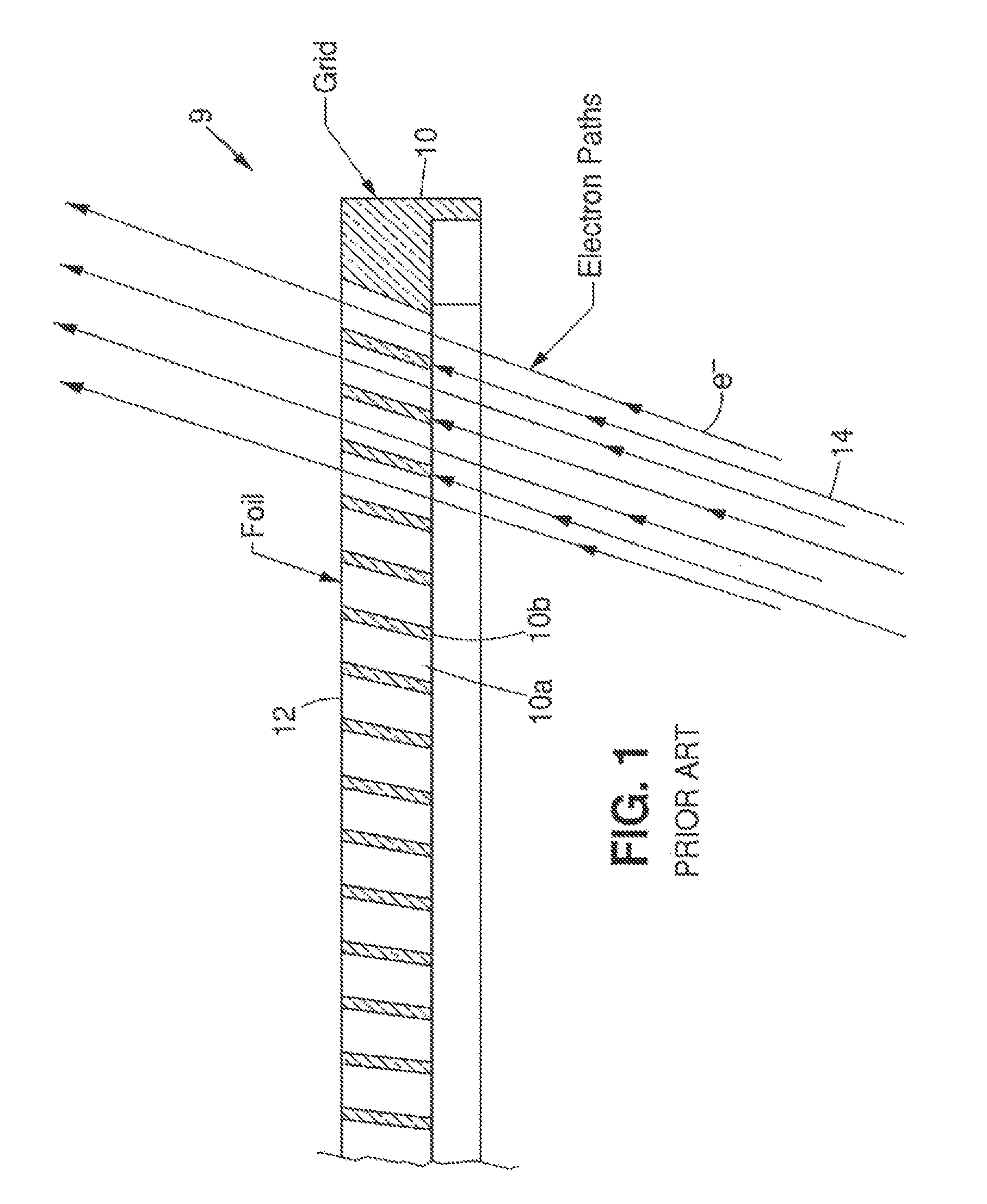
[0022]FIG. 1 depicts a common prior art exit window 9 having a thermally conductive support plate or grid 10 for supporting an exit window foil 12 on an electron beam emitter. The support grid 10 is often copper and the exit window foil is often titanium. The support grid 10 has a series of apertures, holes or openings 10a for allowing passage of electrons e− of an internal electron beam 14 therethrough in order to reach and pass through the exit window foil 12 for emission from the electron beam emitter. Support plate or grid areas 10b between the holes 10a intercept or block a fraction or portion of the electrons e− of the electron beam 14. The amount of the electron beam 14 that is transmitted to or reaches the exit window foil 12 is in proportion to the ratio of the hole area to support plate or grid area normal to electron trajectories. For typical grids, this amount can be in the range of 50% to 80% or more. T...


PUM

PropertyMeasurementUnit
thicknessaaaaaaaaaa
transparentaaaaaaaaaa
beam poweraaaaaaaaaa

Abstract

An exit window can include an exit window foil, and a support grid contacting and supporting the exit window foil. The support grid can have first and second grids, each having respective first and second grid portions that are positioned in an alignment and thermally isolated from each other. The first and second grid portions can each have a series of apertures that are aligned for allowing the passage of a beam therethrough to reach and pass through the exit window foil. The second grid portion can contact the exit window foil. The first grid portion can mask the second grid portion and the exit window foil from heat caused by the beam striking the first grid portion.

Description

RELATED APPLICATION[0001]This application is a continuation of U.S. patent application Ser. No. 12 / 837,814, filed on Jul. 16, 2010, which claims the benefit of U.S. Provisional Application No. 61 / 226,925, filed on Jul. 20, 2009. The entire teachings of the above application are incorporated herein by reference.BACKGROUND[0002]An electron beam emitter typically includes an electron gun or generator, positioned within a vacuum chamber for generating electrons. The generated electrons can exit the vacuum chamber in an electron beam through an electron beam transmission or exit window that is mounted to the vacuum chamber. The exit window commonly has a thin metallic exit window foil, which is supported by a metallic support plate or grid. The support plate has a series of holes which allow electrons to reach and pass through the exit window foil. The support plate dissipates heat from the exit window foil caused by electrons passing through the exit window foil. However, electrons that...

Claims


Application Information

Patent Timeline
Patent Type & Authority Patents(United States)
IPC IPC(8): H01J33/04
CPCH01J33/04G21K5/00H01J5/18Y10T156/10H01J2237/164
Inventor WALTHER, STEVEN R.FRIEDMAN, GERALD M.BUFANO, MICHAEL L.
Owner HITACHI ZOSEN CORP
Why Eureka
Try Eureka