Optical module

a technology of optical modules and optical axes, applied in lasers, laser cooling arrangements, laser details, etc., can solve the problems of degrading performance and increasing the heat dissipation value of optical modules, and achieve the effect of easy suppression of light loss and easy enhancement of alignment precision between the optical axis of solid-state laser devices and the optical axis of wavelength conversion devices

Active Publication Date: 2014-07-08
MITSUBISHI ELECTRIC CORP
View PDF21 Cites 0 Cited by
  • Summary
  • Abstract
  • Description
  • Claims
  • Application Information

AI Technical Summary

Benefits of technology

[0011]According to the optical module of the present invention, among the first block on which the laser medium of the solid-state laser device is mounted, the second block on which the pump light source is mounted, and the third block on which the wavelength converting device is mounted, only the second block is fixed to the board. Therefore, it becomes easy to adjust a relative position of the first block and the third block with respect to the second block. Therefore, it is also easy to align optical axes of at least the laser medium and the wavelength converting device by active alignment with precision of the micrometer order to the sub-micrometer order. Even when a laser resonator for a solid-state laser device is constituted by using the laser medium and the wavelength converting device, it is possible to easily suppress a light loss in the laser resonator.
[0012]Therefore, according to the present invention, it is possible to obtain an optical module in which alignment precision between the optical axis of the solid-state laser device and the optical axis of the wavelength converting device can be easily enhanced, and it becomes easy to obtain a high-output optical module that oscillates laser light of a desired wavelength.

Problems solved by technology

According to the optical module, when a light loss in a laser resonator that constitutes the solid-state laser device is increased, a heating value of the optical module is increased and the performance thereof is degraded.

Method used


Image

  • Optical module
  • Optical module
  • Optical module

Examples


first embodiment

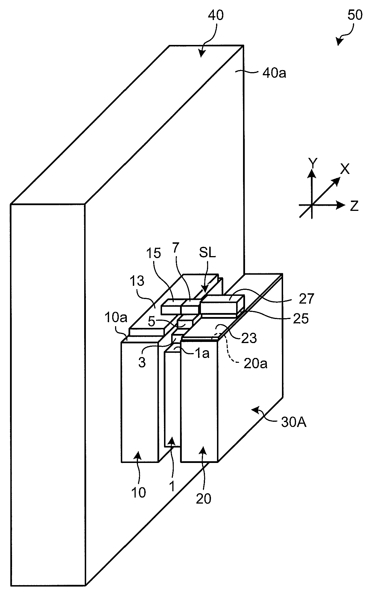
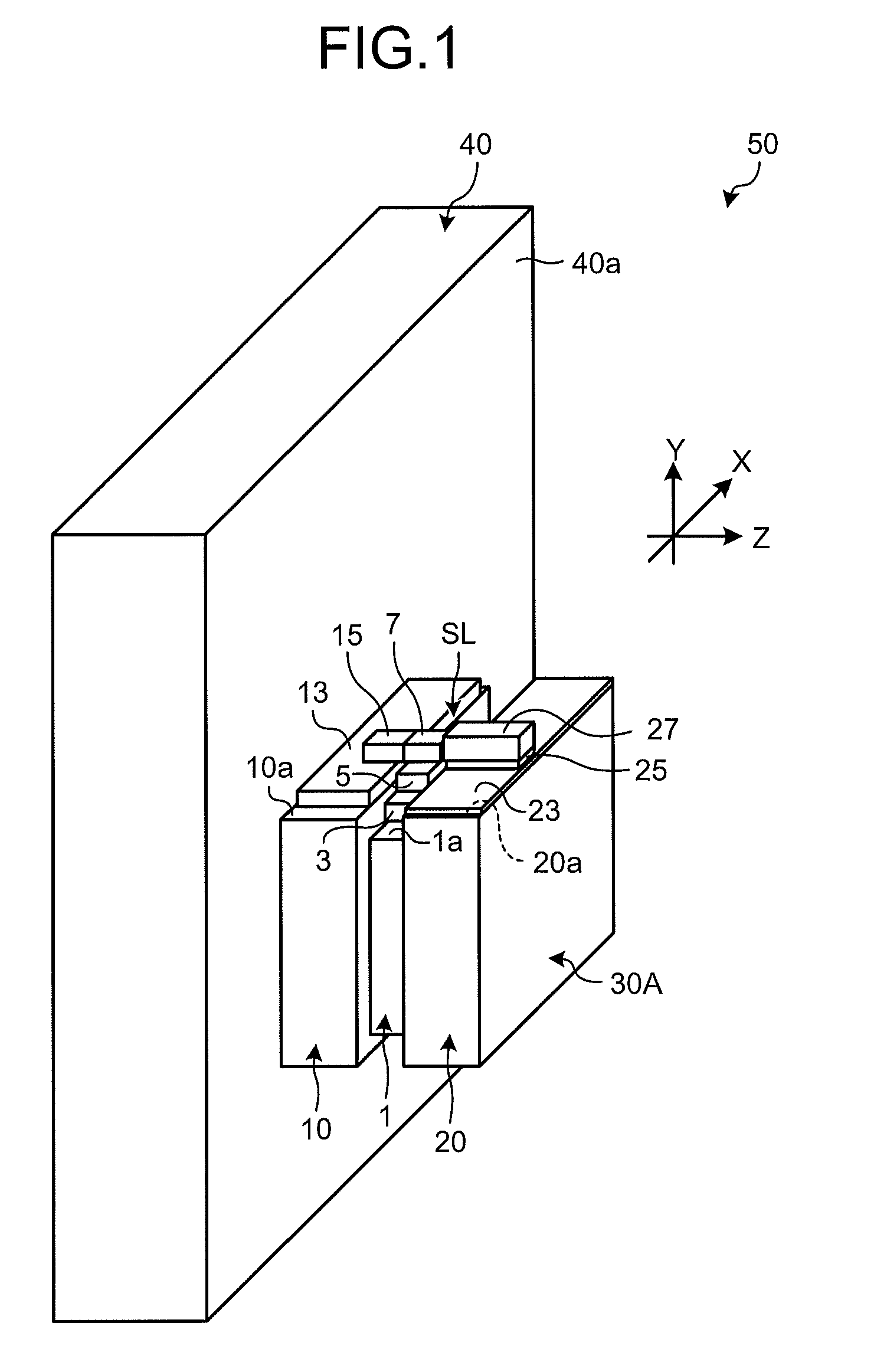
[0033]FIG. 1 is a schematic perspective view of an example of an optical module according to the present invention. An optical module 50 shown in FIG. 1 includes a mount 30A and a board 40. The mount 30A is divided into three blocks, that is, a first block 1, a second block 10, and a third block 20.

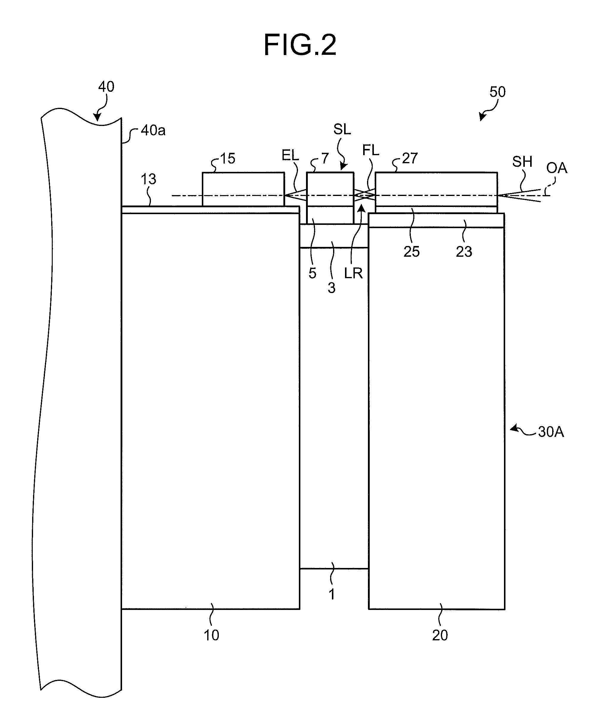
[0034]A thin plate-like stress buffering member 3 is fixed to an upper surface 1a of the first block 1 by a bonding material (not shown). A heat sink 5 is fixed to the stress buffering member 3 by a bonding material (not shown). A laser medium 7 is fixed to the heat sink 5 by a bonding material (not shown). The first block 1 is a flat plate-like member having two side surfaces intersecting with an optical axis of the laser medium 7, and the first block 1 is made of metal or alloy. The stress buffering member 3 relaxes a thermal stress generated by a difference in coefficient of linear expansion between the first block 1 and the heat sink 5.

[0035]The heat sink 5 of the first block 1 forms ...

second embodiment

[0050]The optical module according to the present invention can be formed into a multi-emitter. When the optical module is formed into the multi-emitter, a laser medium having a plurality of optical waveguides is mounted on the upper surface of the first block, a plurality of pump light sources are mounted on the upper surface of the second block, one wavelength converting device in which a plurality of wavelength converting devices or a plurality of optical waveguides are formed is mounted on the upper surface of the third block, wherein the second block is fixed to the board, and the remaining two blocks are fixed to the second block with a predetermined arrangement.

[0051]FIG. 3 is a schematic perspective view of an example of an optical module that is formed into a multi-emitter. An optical module 50A shown in FIG. 3 has the same configuration as that of the optical module 50 shown in FIG. 1, except that the optical module 50A includes a first block 1A, a second block 10A, and a ...

third embodiment

[0055]In the optical module according to the present invention, it is possible to use a light guide that receives pump light from an external light source and emits the pump light toward the laser medium as a pump light source of the laser medium.

[0056]FIG. 4 is a schematic perspective view of an example of an optical module having a light guide as a pump light source of a laser medium. An optical module 150 shown in FIG. 4 has the same configuration as that of the optical module 50 shown in FIG. 1, except that the optical module 150 includes a mount 30B having a second block 110 instead of the second block 10 shown in FIG. 1, and that a bottom surface of the second block 110 is fixed to the board 40. Among constituent elements shown in FIG. 4, elements identical to those shown in FIG. 1 are denoted by like reference letters or numerals used in FIG. 1, and explanations thereof will be omitted.

[0057]A light guide 113 is fixed to an upper surface 110a of the second block 110 by a bond...


PUM


Abstract

To constitute an optical module comprising a mount and a board that supports the mount, wherein a solid-state laser device that oscillates fundamental laser light, a pump light source that pumps the solid-state laser device, and a wavelength converting device that converts a wavelength of the fundamental laser light oscillated by the solid-state laser device are mounted on the mount, the mount is divided into three blocks, that is, a first block on which a laser medium is mounted, a second block on which the pump light source is mounted, and a third block on which the wavelength converting device is mounted. A side surface or a bottom surface of only the second block is fixed to the board, the first block is fixed to the other side surface of the second block, and the third block is fixed to a side surface of the first block.

Description

TECHNICAL FIELD[0001]The present invention relates to an optical module that converts fundamental laser light oscillated from a laser device into laser light having a predetermined wavelength by a wavelength converting device and outputs the laser light.BACKGROUND ART[0002]To obtain an optical module that oscillates green laser light of a wavelength 530-nm band, infrared laser light of a 1060-nm band is used as fundamental laser light, and the wavelength of the fundamental laser light is converted by a wavelength converting device in many cases. Therefore, the optical module that oscillates green laser light generally includes a solid-state laser device that oscillates fundamental laser light, a pump light source that pumps the solid-state laser device, and a wavelength converting device.[0003]According to the optical module, when a light loss in a laser resonator that constitutes the solid-state laser device is increased, a heating value of the optical module is increased and the p...

Claims


Application Information

Patent Timeline
Patent Type & Authority Patents(United States)
IPC IPC(8): H01S3/04
CPCH01S3/025H01S3/0092H01S3/042H01S3/094053H01S3/09415H01S3/1611H01S3/1673
Inventor NAKAMURA, AKIRAOKAMURA, MASAMITSUFUKUDA, KEIICHINANBA, CHISEIKEDA, KAZUTAKA
Owner MITSUBISHI ELECTRIC CORP
Why Eureka
Try Eureka