
Regenerator for a thermal cycle engine

a technology of thermal cycle engine and generator, which is applied in the direction of machines/engines, indirect heat exchangers, lighting and heating apparatus, etc., can solve the problems of minimal pressure drop and high air permeability, and achieve the effect of avoiding preferential airflow

Inactive Publication Date: 2014-07-22
NV BEKAERT SA
View PDF39 Cites 1 Cited by
  • Summary
  • Abstract
  • Description
  • Claims
  • Application Information

AI Technical Summary

Benefits of technology

This patent is about improving regenerators for thermal cycle engines like stirling engines. The invention achieves this by using fibers, especially metal fibers, with a high degree of porosity (70-99%) which increases air permeability. This high air permeability results in a minimal pressure drop and allows for a seamless filling of the regenerator space, preventing preferential airflows. The use of wound fiber bundles in the regenerator also improves thermal conductivity and allows for a faster heat movement with the working fluid. Overall, this invention design creates more efficient and effective regenerators for thermal cycle engines.

Problems solved by technology

This high porosity results in a high air permeability.
This high air permeability results in a minimal pressure drop.

Method used

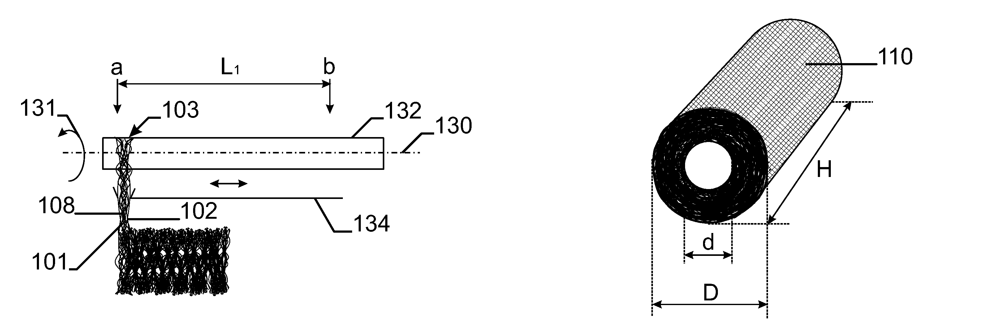
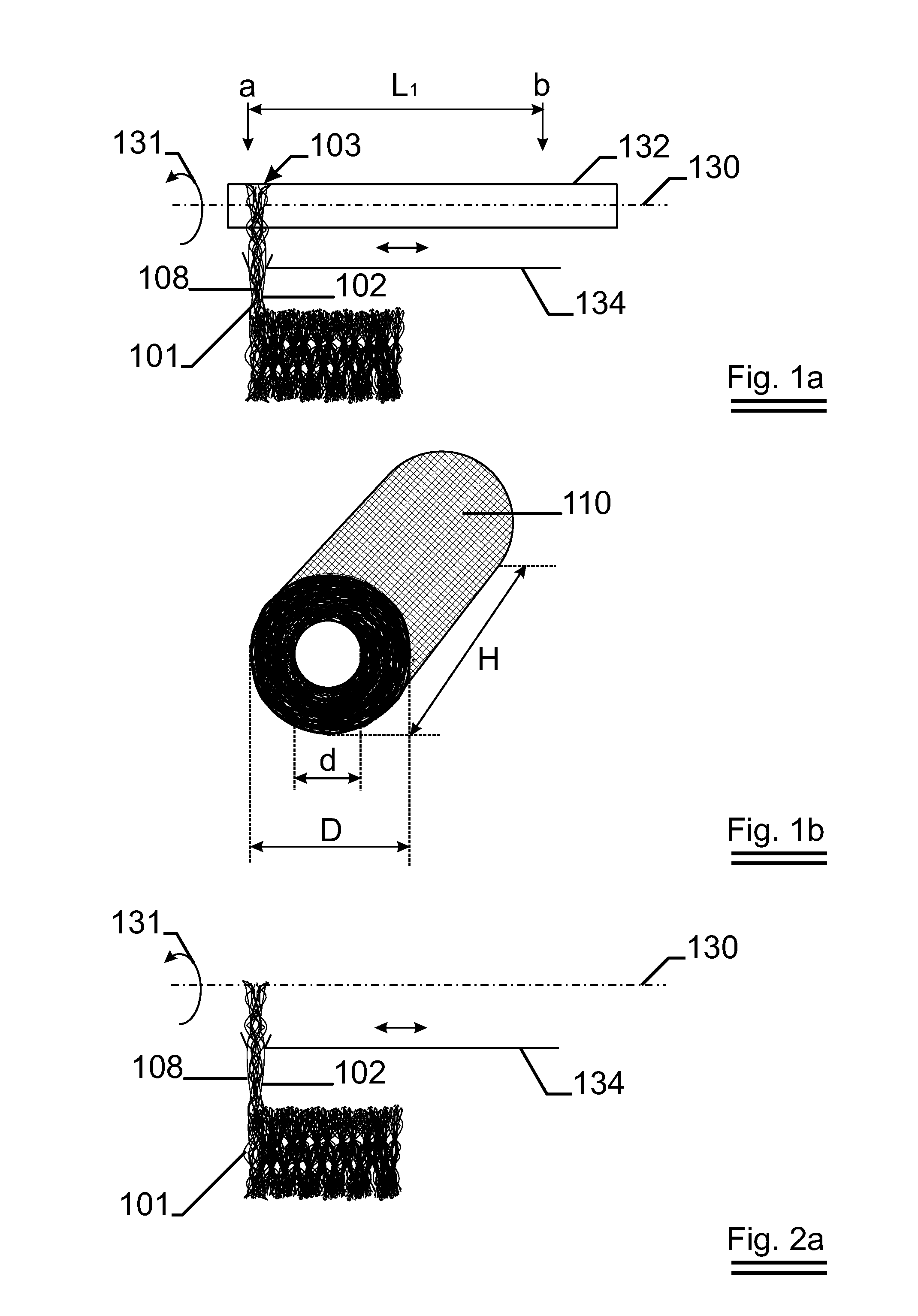
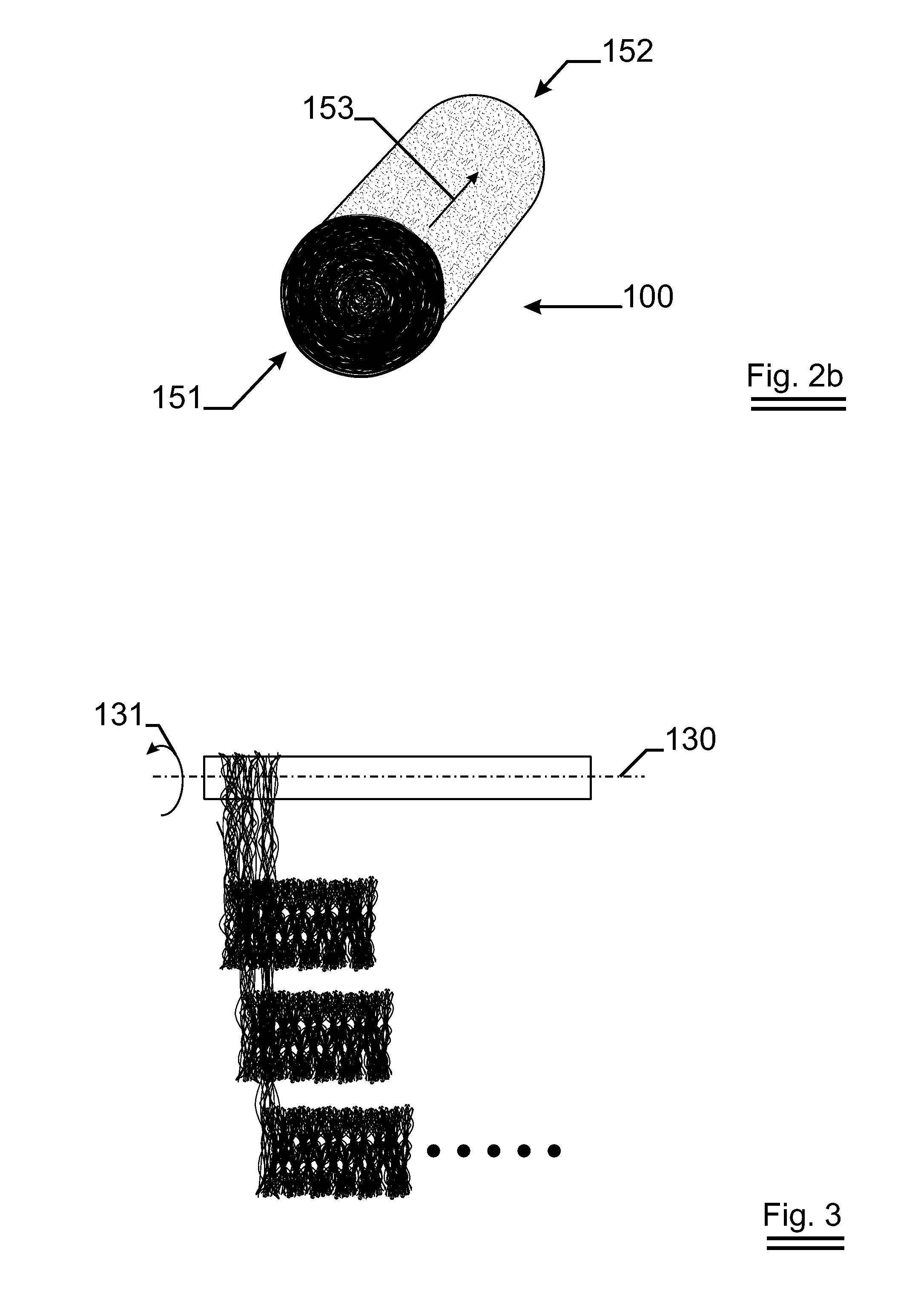

Image

  • Regenerator for a thermal cycle engine
  • Regenerator for a thermal cycle engine
  • Regenerator for a thermal cycle engine

Examples


Embodiment Construction

[0054]The present invention will be described with respect to particular embodiments and with reference to certain drawings but the invention is not limited thereto but only by the claims. The drawings described are only schematic and are non-limiting. In the drawings, the size of some of the elements may be exaggerated and not drawn on scale for illustrative purposes. The dimensions and the relative dimensions do not correspond to actual reductions to practice of the invention.

[0055]Furthermore, the terms first, second, third and the like in the description and in the claims, are used for distinguishing between similar elements and not necessarily for describing a sequence, either temporally, spatially, in ranking or in any other manner. It is to be understood that the terms so used are interchangeable under appropriate circumstances and that the embodiments of the invention described herein are capable of operation in other sequences than described or illustrated herein. Moreover,...


PUM

PropertyMeasurementUnit
length Lfiberaaaaaaaaaa
porosityaaaaaaaaaa
porosityaaaaaaaaaa

Abstract

A regenerator (100), for a thermal cycle engine with external combustion, according to the invention comprises a network of metal fibers wherein a majority of the fibers at least partially encircles the axis of the regenerator. The fibers were part of a fiber bundle which is coiled and sintered thereby obtaining the regenerator.

Description

TECHNICAL FIELD[0001]The present invention relates to a regenerator for a thermal cycle engine with external combustion, such as a Stirling cycle heat engine. More in particular, the present invention relates to an improved regenerator for a thermal cycle engine.[0002]The invention further relates to methods for obtaining such a regenerator and the use of such regenerator in a thermal cycle engine.BACKGROUND ART[0003]A regenerator is used in a thermal cycle machine to add and remove heat from the working fluid during different phases of the thermal cycle. Such regenerators must be capable of high heat transfer rates which typically suggests a high heat transfer area and low flow resistance to the working fluid.[0004]Different types of regenerators are already available on the market. Typically such regenerators comprise metal screens, cylindrically wound wire gauze or 3D random fiber networks as e.g. described in JP1240760, JP2091463 and WO01 / 65099; or even short metal fibers as e.g...

Claims


Application Information

Patent Timeline
Patent Type & Authority Patents(United States)
IPC IPC(8): F01B29/10
CPCF02G1/057F02G2257/00F28D17/02Y10T29/49357Y10T29/4935
Inventor VERSCHAEVE, FRANKSCHILDERMANS, INGE
Owner NV BEKAERT SA
Learn More