Low EMF compact duct spacer

a compact, duct spacer technology, applied in the direction of cable installation in underground tubes, machine supports, cables, etc., can solve the problems of deformation or crushing of conduits, heavy loads on the duct bank, and no studies or evidence available to date have conclusively proven that exposure to emf above 3 to 4 mg is detrimental to human health

Active Publication Date: 2014-07-22
UNDERGROUND DEVICES
View PDF57 Cites 20 Cited by
  • Summary
  • Abstract
  • Description
  • Claims
  • Application Information

AI Technical Summary

Problems solved by technology

Backfill, roads, railroads and the like are placed on top of the duct bank, resulting in heavy loads on the duct bank.
Irregular movement caused by settling would otherwise deform or crush the conduits.
None of the studies or evidence available to date has conclusively proven that exposure to an EMF above 3 to 4 mG is detrimental to human health.

Method used


Image

  • Low EMF compact duct spacer
  • Low EMF compact duct spacer
  • Low EMF compact duct spacer

Examples


first embodiment

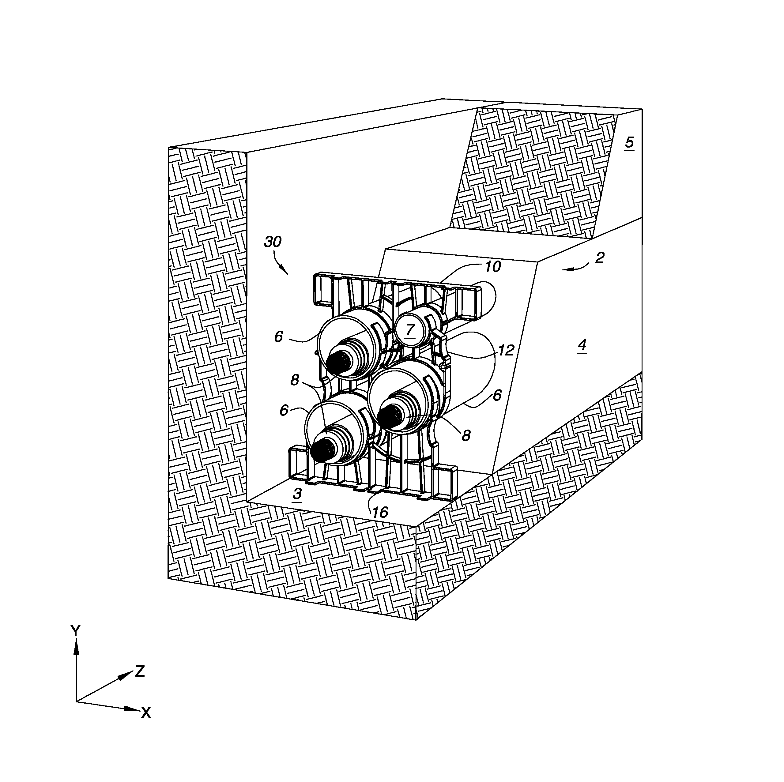
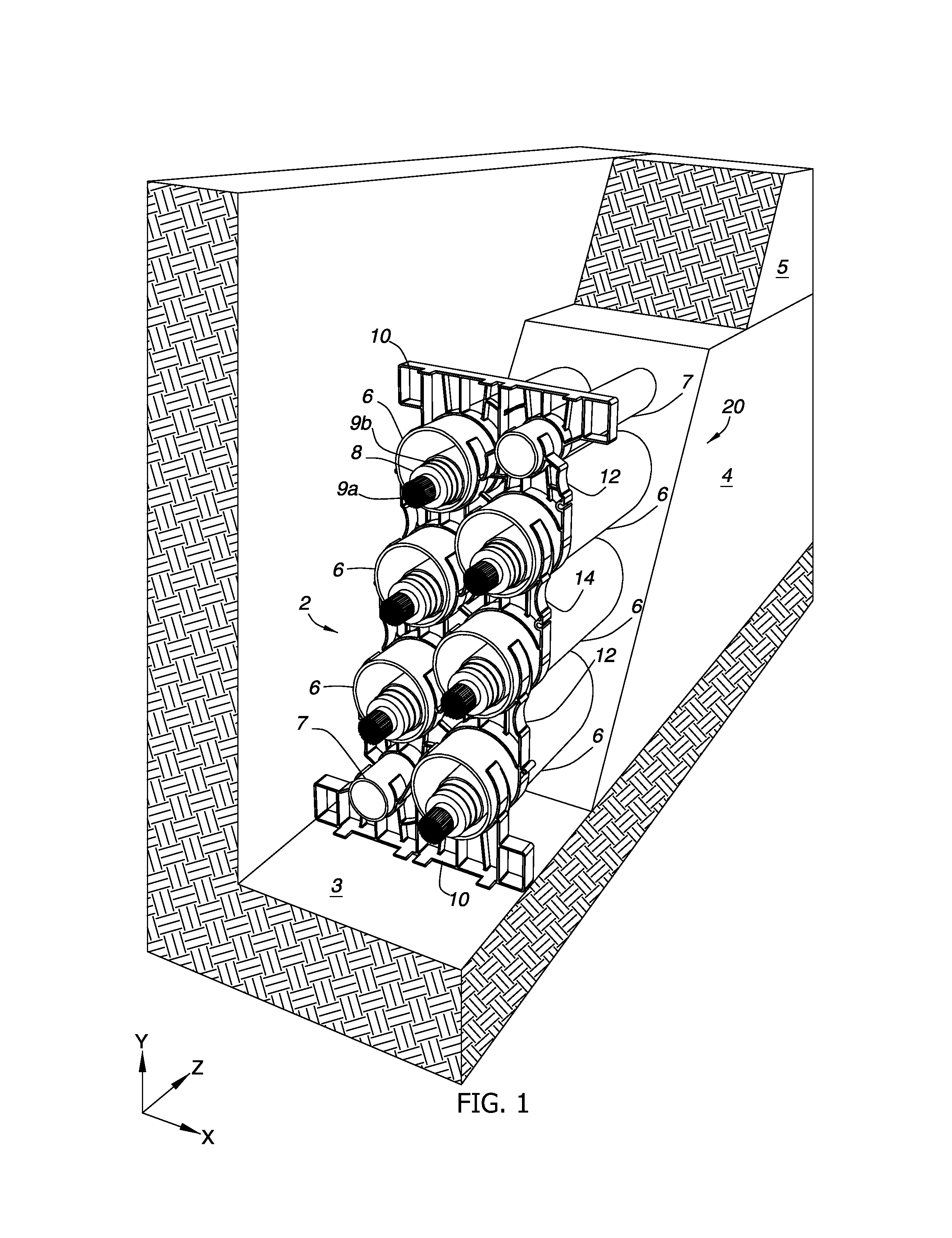
[0060]A first embodiment duct bank with the spacers described herein is presented in the perspective view of FIG. 1. The installation includes a duct bank 2 which has been placed in a trench 3 and then encased in protective concrete 4. After the concrete cures, the installation is backfilled with the overburden or earth 5 that was previously removed. Duct bank 2 includes a plurality of large conduits 6 and small conduits 7. The conduits are stacked atop each other as shown using duct spacers 10, 12, 14, 12 and 10. The duct spacers are staggered horizontally to avoid creation of a vertical shear plane in the concrete. The figure depicts spacers suitable for a dual 3-phase arrangement 20 of power cables to be placed into the large conduits shown. The smaller conduits are typically not used for power cable, but may instead be used for fiber optic communications cables, control cables and thermocouples or other temperature elements for monitoring duct bank temperatures. The smaller cond...

embodiment 50

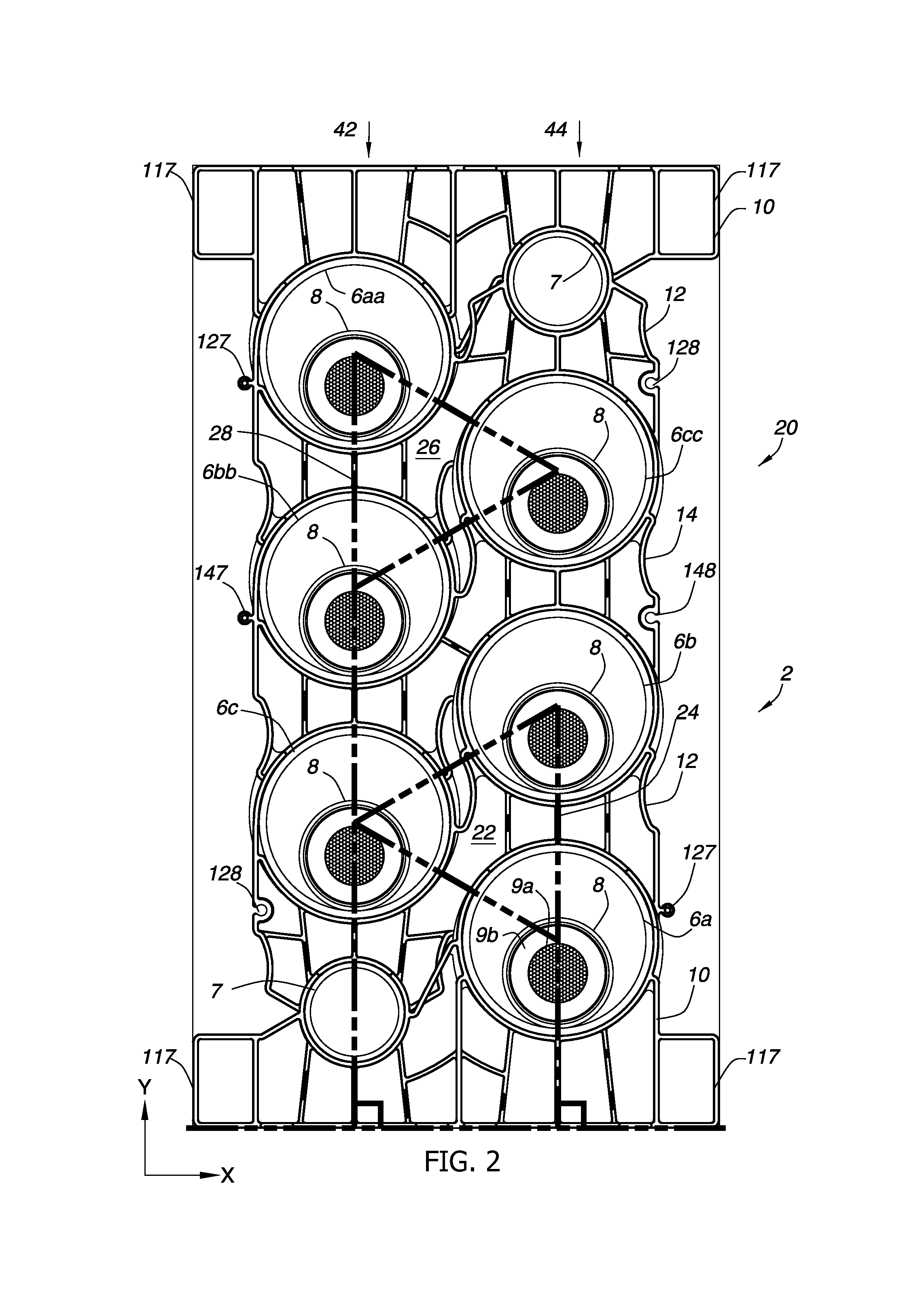
[0078]FIGS. 9-10, for example, depict the same arrangement 20 of dual 3-phase transmission lines discussed above, with conduits and cables spaced in an equilateral triangle 22, 26 arrangement with bases 24, 28 roughly perpendicular to the bottom of trench 3 or the ground. In this embodiment 50, a single spacer body 50a is supported by a spacer base 50b on the bottom of a trench 3. In one embodiment, spacer body 50a is fabricated from 0.5 inch thick HDPE sheet stock using a CNC router. Alternatively, spacer 50a could be injection molded for a lower cost if volume warrants. Spacer body 50a is joined to spacer base 50b with a slit 50c in the base. When the installation is complete, the duct bank 2 is encased in concrete 4 and then covered with overburden 5, such as with earth. Single spacer body 50a may be any suitable width, such as ¼″ to ½″, although embodiments may use widths that are greater or narrower than these.

[0079]Spacer body 50a may be a sheet of plastic or composite materia...


PUM

PropertyMeasurementUnit
voltageaaaaaaaaaa
voltageaaaaaaaaaa
voltageaaaaaaaaaa

Abstract

Conduit spacers useful in preparing duct banks with reduced electromagnetic fields (EMF) are disclosed. The conduit spacers are designed to maximize phase cancellation of EMF from a closely-spaced series of electric power cables placed in conduits supported underground by the conduit spacers. The spacers are also designed to minimize the EMF above ground by reducing the distance needed to bury the cables for a given EMF above ground. In one embodiment, the spacers place conduits adjacent one another for maximum cancellation of a single three-phase cable installation. In another embodiment, the spacers place conduits adjacent one another for maximum cancellation for a dual three-phase cable installation, including cross-phase cancellation, e.g., A-B-C and C-B-A.

Description

TECHNICAL FIELD[0001]This application claims priority to, and the benefit of, U.S. Non-provisional Appl. 61 / 678,946, filed 2 Aug. 2012, which is hereby incorporated by reference in its entirety.TECHNICAL FIELD[0002]The technical field is that of methods and apparatus for separating and supporting power and communication conduits in underground trenches in order to minimize electromagnetic field emissions.BACKGROUND[0003]Electric-power transmission is the bulk transfer of electrical energy from generating power plants to electrical substations. Most transmission lines use high-voltage three-phase alternating current (AC) that requires three conductors (three cables). Three-phase alternating current (AC) is used because it can be transmitted at high voltages (110 kV or above) or extra high voltage (230 kV to 765 kV) to reduce the energy lost in long-distance transmission. Using transformers, the electricity can then be efficiently reduced to sub-transmission level (33 kV to 132 kV) an...

Claims


Application Information

Patent Timeline
Patent Type & Authority Patents(United States)
IPC IPC(8): H02G1/08H02G9/06F16L3/02F16L3/22
CPCF16L3/02H02G9/06H02G1/08Y10T29/49117F16L3/2235H02G3/02
Inventor MCCOY, DONALD, P
Owner UNDERGROUND DEVICES
Why Eureka
Try Eureka