Frameless track assembly

a technology of frameless track and support assembly, which is applied in the direction of hoisting equipment, mechanical control devices, instruments, etc., can solve the problems of inconvenient movement in the terrain where equipment is used, and achieve the effect of reducing the difficulty of movemen

Active Publication Date: 2014-07-22
BRAZIER GLEN
View PDF12 Cites 5 Cited by
  • Summary
  • Abstract
  • Description
  • Claims
  • Application Information

AI Technical Summary

Benefits of technology

[0010]It is a further object of the invention to mount rollers to support the sprocket to prevent slippage or dislodgement of the sprocket from the track and / or from contact with the idler wheels.
[0011]It is a further object of the invention to provide idler wheels that include integrated seals that cooperate with sprocket support rollers and / or the sprocket to prevent the collection of abrasive materials at overlapping rotating surfaces.
[0012]It is a further object of the invention to provide idler wheels that contain and support the sprocket in tensioned contact with the track to prevent slippage or dislodgement of the track from the idler wheels and / or sprocket.
[0013]It is a further object of the invention to provide a stabilizer linkage that couples to and / or extends between axles that support idler wheels and / or sprocket support rollers to stabilize the idler wheels and / or sprocket and / or drive lugs depending from a drive track surface against lateral movement and dislodgement of the track.
[0020]An alternative track tensioning assembly is also disclosed that comprises a sprocket support roller having an off-center axle bore. An idler axle keyed to a fasteners fashioned to mate at multiple positions at the stabilizer linkages is mounted to rotate the support roller relative to a stabilizer linkage arms in an eccentric fashion to displace the roller and sprocket to vary the tension between the sprocket and track. Upon securing the axle fasteners and ends of the idler axle to available locking positions, the selected track tension is sustained.

Problems solved by technology

The terrain where the equipment is used however is not always accommodating of movement of the wheels through mud, snow and over other rough terrain.

Method used


Image

  • Frameless track assembly
  • Frameless track assembly
  • Frameless track assembly

Examples


Embodiment Construction

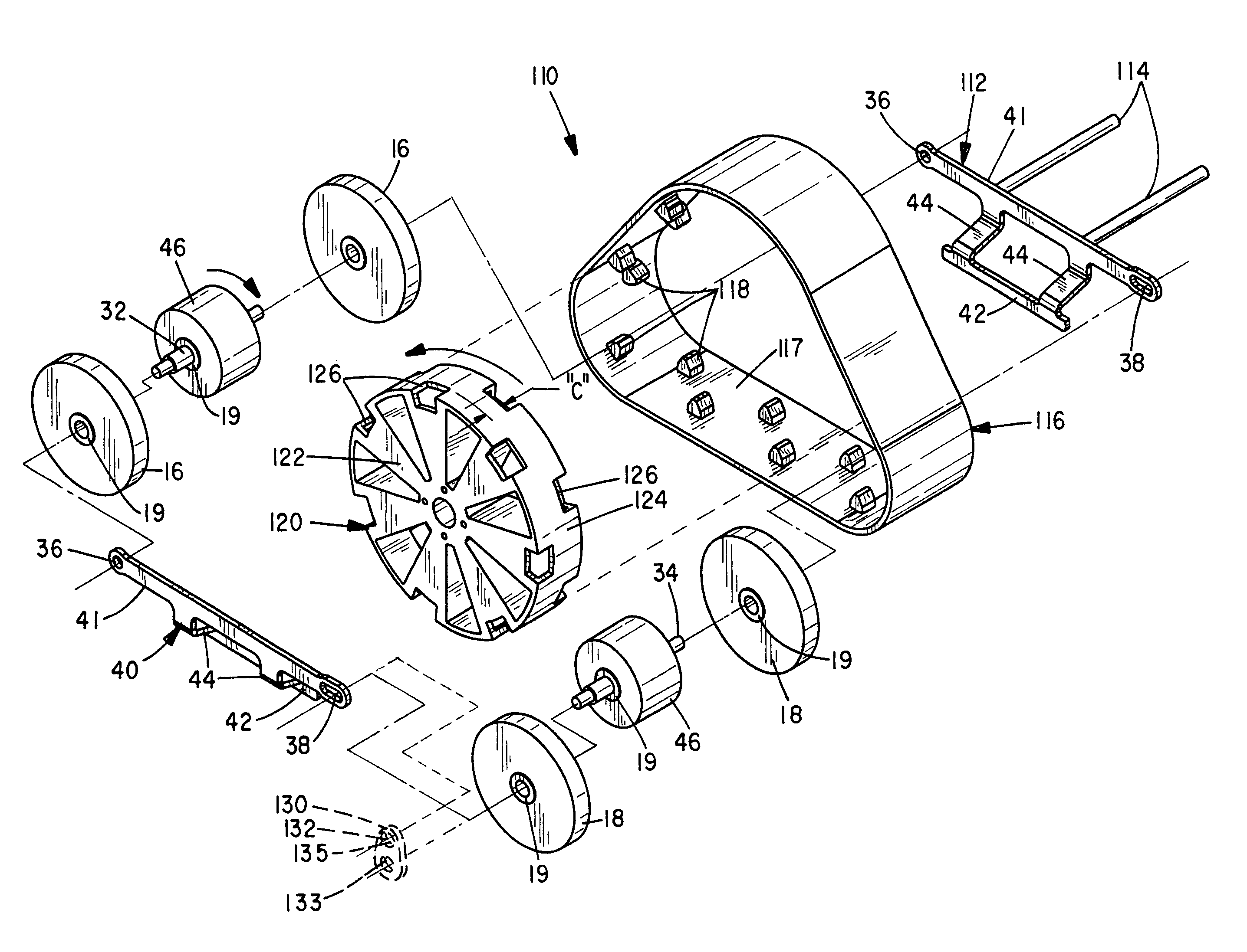
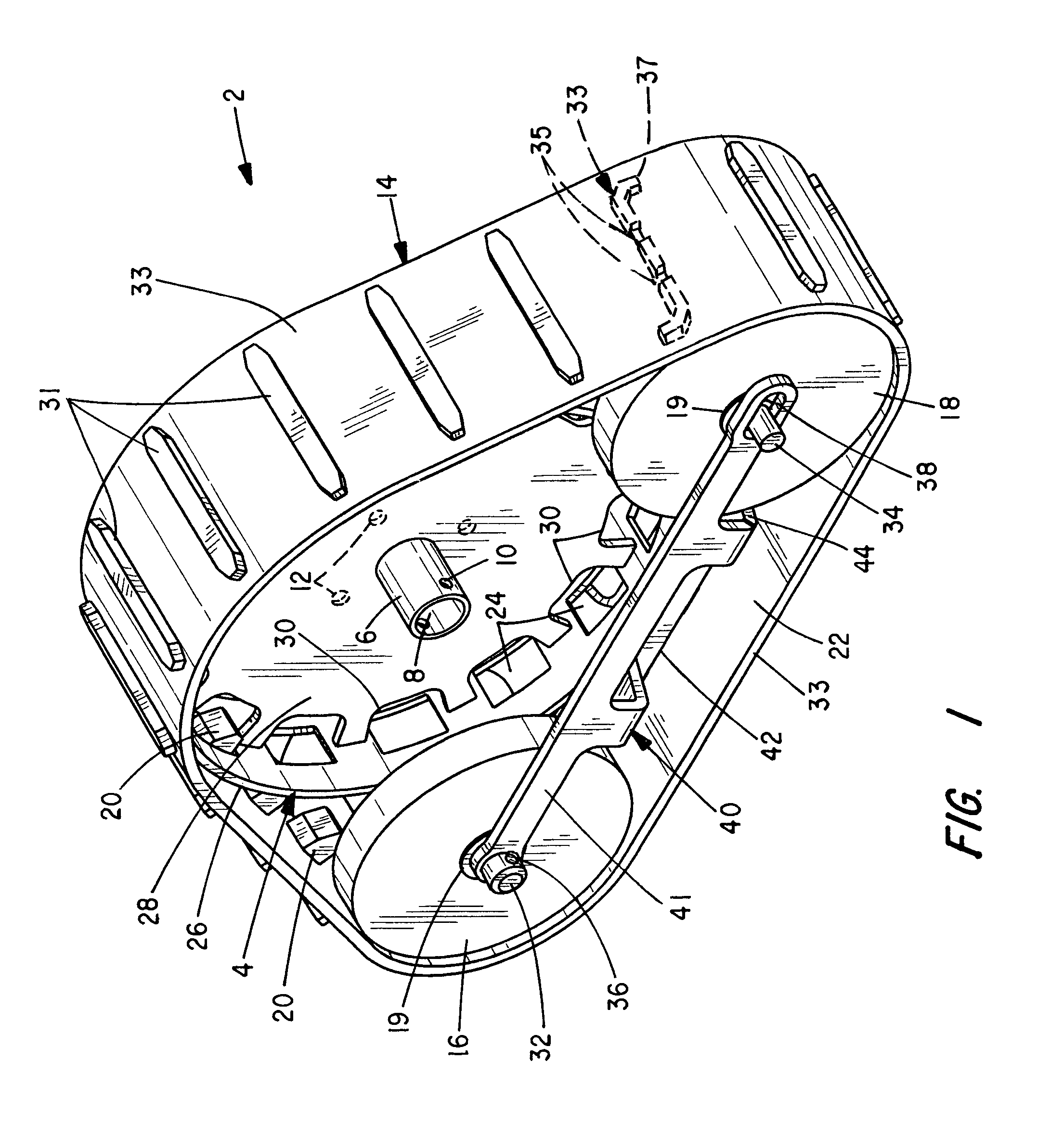
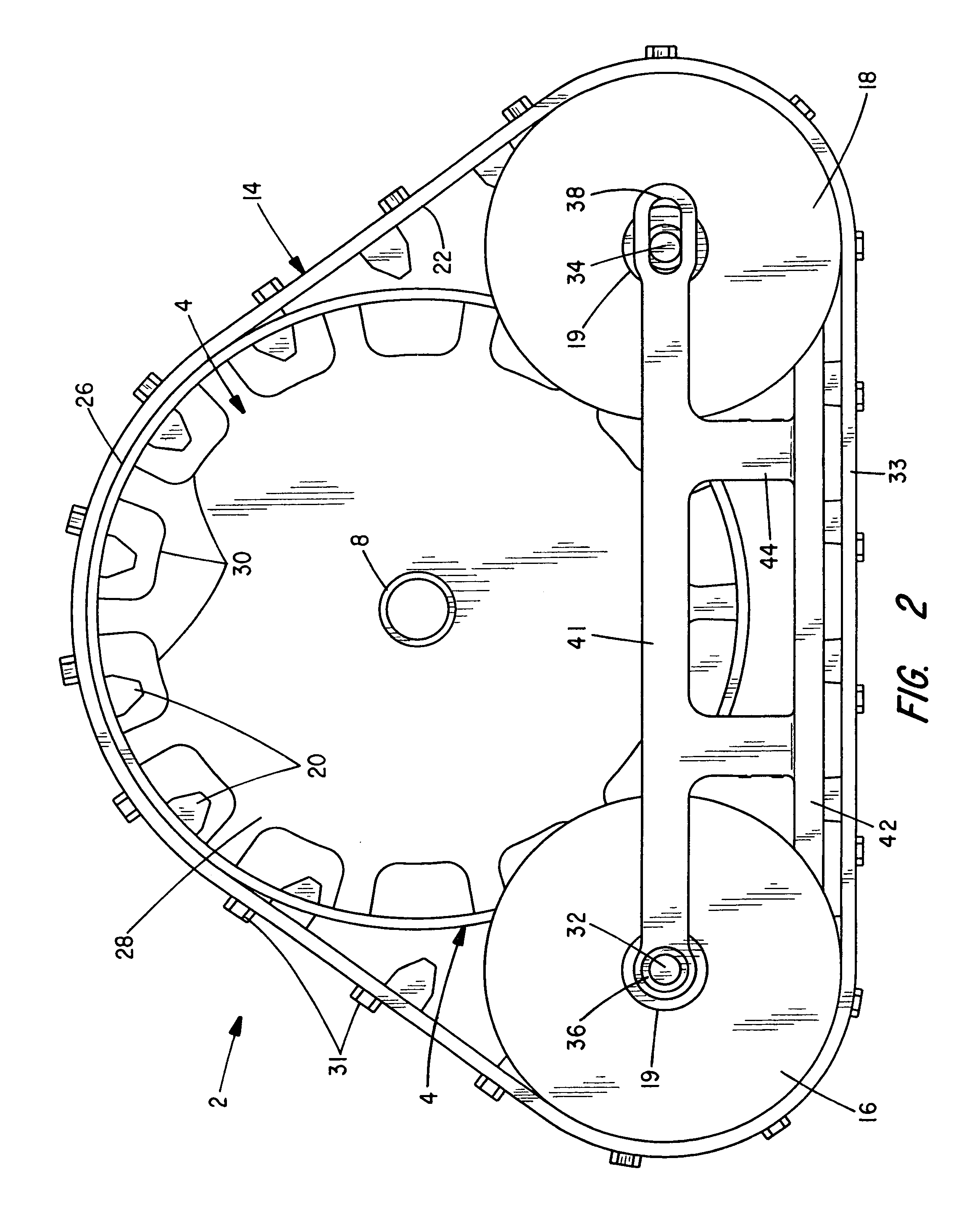
[0039]With attention to the perspective view of FIG. 1, an improved frameless track assembly 2 of the invention is shown. The assembly 2 finds utility with a variety of passive and self-driven power equipment for commercial, contractor and home use, such as snow blowers, lawn equipment, trenchers, bucket-type diggers etc. Multiple track assemblies 2 are typically mounted to support the equipment alone or in combination with wheels or other supports.

[0040]A sprocket 4 of the assembly 2 is adapted to rotate and couple to a passive (i.e. un-powered) axle, driven axle or power takeoff (PTO) device or linkage (not shown) provided at the equipment. A hub 6 having a central bore 8 and transverse fastener holes 10 projects from the sprocket 4 and receives an axle or a power driven shaft (not shown).

[0041]The driven shaft is commonly coupled to an equipment engine via a geared transmission, belt system, hydrostatic coupler or other suitable power transfer linkage. The holes 10 align with mat...


PUM


Abstract

A track assembly comprising an endless track trained about a sprocket and forward and aft sets of idler wheels. A plurality of apertures at the sprocket engage drive lugs that project from an interior track surface. Longitudinal stabilizer arms restrain the idler wheel axles, idler wheels, sprocket support rollers, sprocket and track against lateral movement and tension the track. Overlapping seals are formed at the idler wheels and / or sprocket support rollers. Alternative sprockets having cutouts or pockets that capture different drive lug configurations are also disclosed along with several alternative track tensioning assemblies that rotate in an eccentric fashion to tension the track.

Description

BACKGROUND OF THE INVENTION[0001]The present invention relates to a track support assembly for motorized equipment and, in particular, to an endless track assembly particularly adapted to support snow blowers and other light weight equipment.[0002]A wide variety of engine powered equipment has been developed for performing a variety of home and commercial tasks, for example, snow blowers, plows, grass cutters, sweepers, trenchers, bucket-type diggers, stump grinders, among other equipment types. The chassis and frameworks of such equipment are typically supported on wheels mounted with pneumatic tires. The terrain where the equipment is used however is not always accommodating of movement of the wheels through mud, snow and over other rough terrain. Many of these units also include self-drive linkages.[0003]The present invention was developed to provide an economical, self-supporting and substantially frame-less track assembly for such equipment and especially self-driven equipment....

Claims


Application Information

Patent Timeline
Patent Type & Authority Patents(United States)
IPC IPC(8): B62D55/08B62D55/14
CPCB62D55/30B62D55/14B62D55/244B62D55/12B62D55/08
Inventor BRAZIER, GLEN
Owner BRAZIER GLEN
Why Eureka
Try Eureka