Engine intake system

a technology of engine oil intake and intake tube, which is applied in the direction of engine controllers, electric control, combustion engines, etc., can solve the problems of increasing engine oil consumption and environmental pollution, and achieve the effect of effectively coping and reliably detecting the disconnection of the blow-by gas return tub

Inactive Publication Date: 2014-07-29
HINO MOTORS LTD
View PDF13 Cites 7 Cited by
  • Summary
  • Abstract
  • Description
  • Claims
  • Application Information

AI Technical Summary

Benefits of technology

[0017]According to the engine intake system of the invention, there can be obtained advantageous effects of reliably detecting disconnection of the blow-by gas return tube and of effectively coping with, e.g., forgetting to connect the blow-by gas return tube after completion of maintenance.

Problems solved by technology

Accordingly, mere release of the blow-by gas to the atmosphere results in discharge of also the oil mist mixed with the blow-by gas to outside, leading to increase in engine oil consumption as well as to environmental pollution.

Method used


Image

  • Engine intake system
  • Engine intake system
  • Engine intake system

Examples


Embodiment Construction

[0021]An embodiment of the invention will be described with reference to the accompanying drawings.

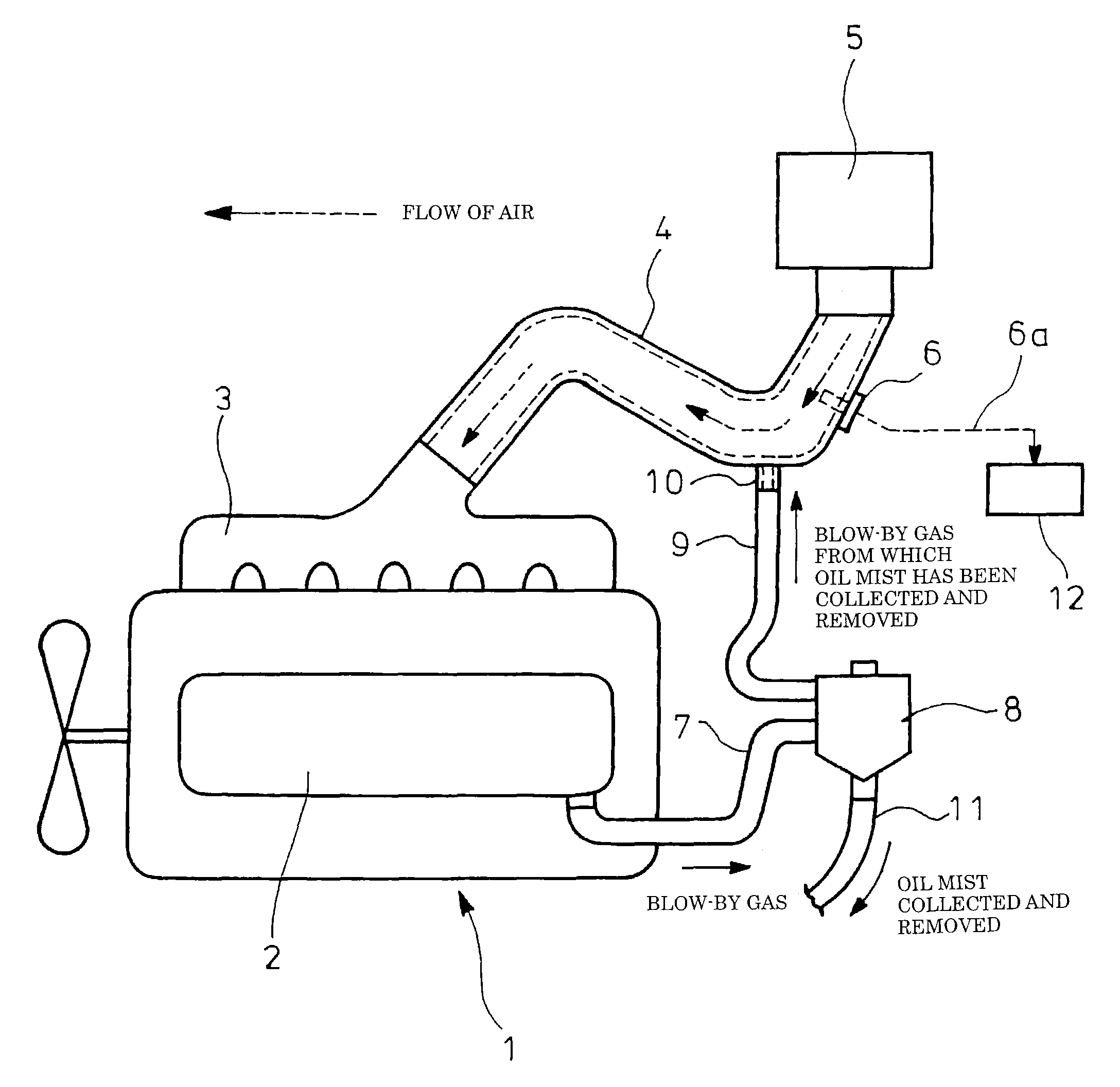
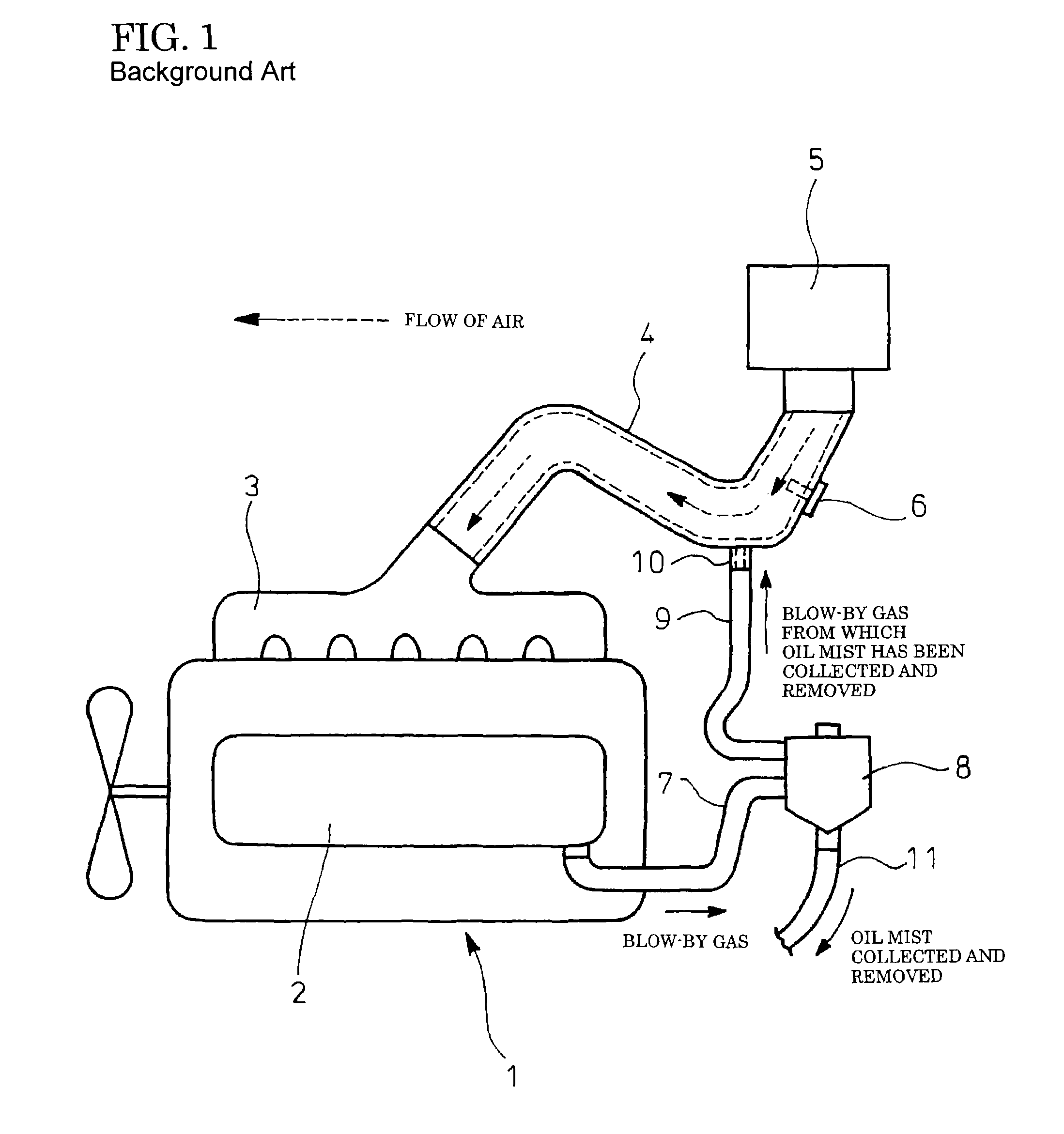
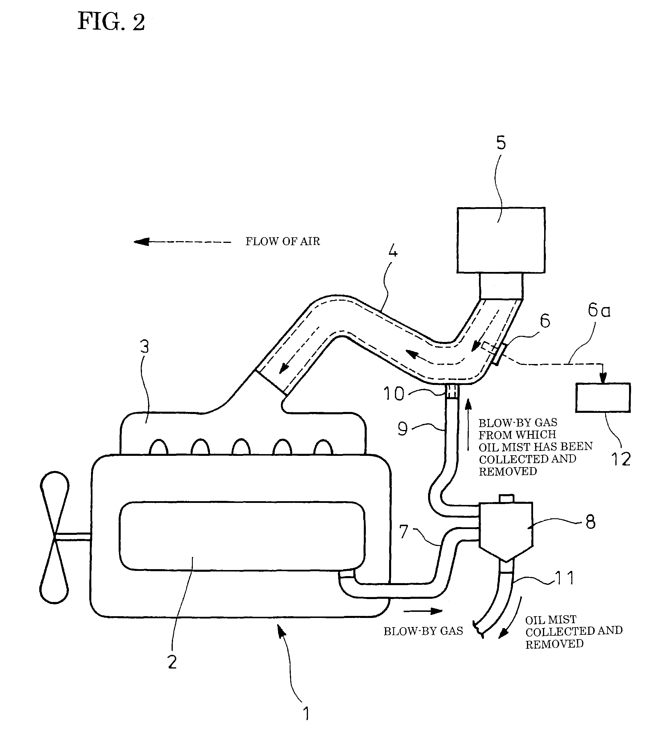
[0022]FIGS. 2 and 3 show the embodiment of the invention in which equivalents to those shown in FIG. 1 are represented by the same reference numerals. The embodiment has a basic configuration similar to that of the conventional example and resides as shown in FIGS. 2 and 3 in the provision of a controller 12 which calculates an idling intake air quantity Q on the basis of an air flow rate 6a measured by an airflow meter 6 and which determines disconnection of the blow-by return tube 9 in a case where a value (Q0−Q) obtained by subtracting the idling intake air quantity Q from a stored normal intake air quantity Q0.

[0023]In the embodiment, the controller 12 provides controls as shown in FIG. 3. At step S1, start of the diesel engine body 1 is recognized. At step S2, an idling intake air quantity Q is calculated through an averaging process for several seconds on the basis of an air flow...


PUM


Abstract

An engine intake system is provided with a controller for calculating an idling intake air quantity on the basis of an air flow rate measured by an airflow meter and determining disconnection of a blow-by gas return tube in a case where a value obtained by subtracting the idling intake air quantity from a stored normal intake air quantity exceeds a threshold.

Description

TECHNICAL FIELD[0001]The present invention relates to an engine intake system.BACKGROUND ART[0002]A gas leaking through a gap of a piston ring into a crankcase during engine compression and explosion strokes is generally called blow-by gas. The blow-by gas, which fills the crankcase and a cylinder head cover communicating therewith, needs to be released outside.[0003]However, the crankcase has therein a crankshaft, a connecting rod and the like which move fast, and the cylinder head cover communicating with the crankcase has therein a rocker arm, a valve and the like which are in work, so that the crankcase and the cylinder head cover are full of oil mist.[0004]Accordingly, mere release of the blow-by gas to the atmosphere results in discharge of also the oil mist mixed with the blow-by gas to outside, leading to increase in engine oil consumption as well as to environmental pollution. For these reasons, a recent diesel engine is also provided with a closed breather which is operate...

Claims


Application Information

Patent Timeline
Patent Type & Authority Patents(United States)
IPC IPC(8): F01M13/00
CPCF01M13/04F01M13/022F02D41/083F02D41/18F02D2200/0402
Inventor NARITA, HIRONORI
Owner HINO MOTORS LTD
Why Eureka
Try Eureka