Twin clutch transmission, and vehicle equipped therewith

a transmission and clutch technology, applied in the direction of crankshaft transmission, frictional roller based transmission, gearing, etc., can solve problems affecting good driving conditions

Inactive Publication Date: 2014-08-05
YAMAHA MOTOR CO LTD
View PDF23 Cites 4 Cited by
  • Summary
  • Abstract
  • Description
  • Claims
  • Application Information

AI Technical Summary

Benefits of technology

[0010]According to a preferred embodiment of the present invention, a twin clutch transmission is provided that maintains good driving conditions and a vehicle equipped therewith.
[0013]According to the preferred embodiments of the present invention, it is possible to maintain good driving conditions even when using twin clutches.

Problems solved by technology

However, if, as described above, a configuration is employed in which power is transferred to an output shaft by selecting between power transfer paths of two separate systems using two clutches, without blocking the transfer of power, there is the possibility that, if a clutch is switched at the wrong timing, gears are interlocked between the first and second main shafts and the countershaft, and might affect good driving conditions.

Method used


Image

  • Twin clutch transmission, and vehicle equipped therewith
  • Twin clutch transmission, and vehicle equipped therewith
  • Twin clutch transmission, and vehicle equipped therewith

Examples


case 770

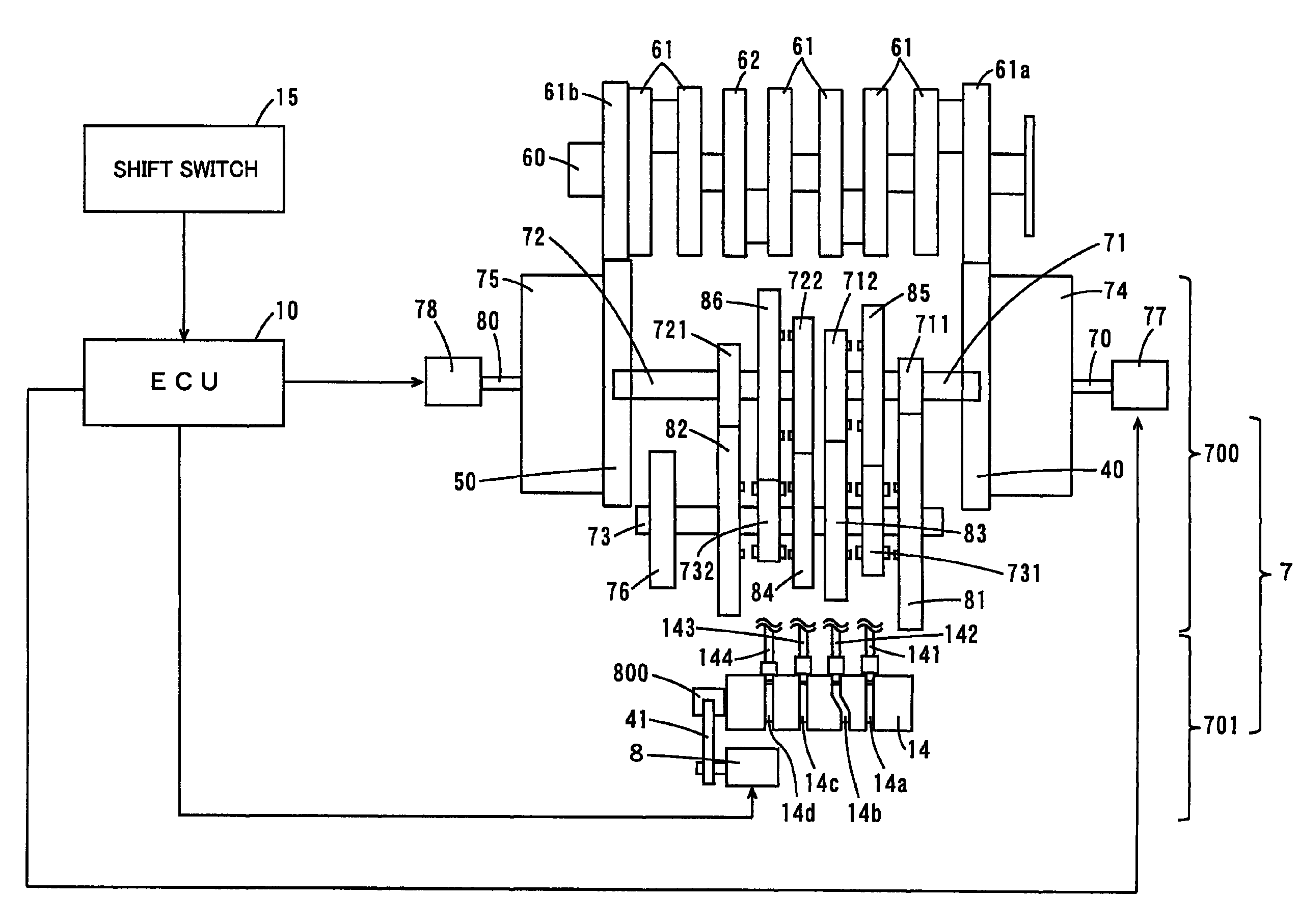
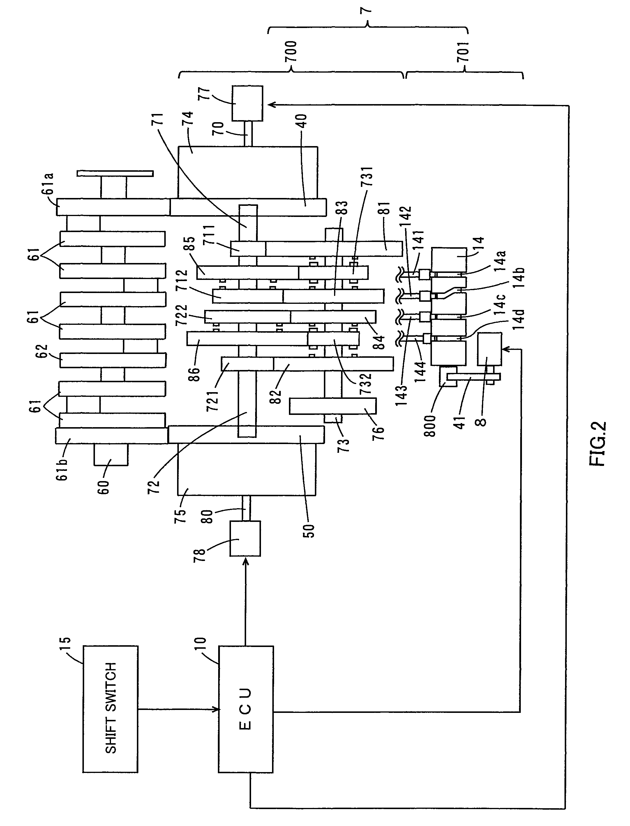
[0101]Mission case 770 is arranged parallel or substantially parallel to the direction in which shaft accommodating section 921 extends in crank case 92. Mission case 770 accommodates portions of first and second main shafts 71 and 72, drive shaft 73, and gears through 86, 711, 712, 721, 722, 731, and 732.

[0102]Side cover sections 770a and 770b each preferably have a bell shape, and cover first clutch 74 and second clutch 75 from both sides (the left and right sides) of crank case 92.

[0103]Of side cover sections 770a and 770b, one (left side) side cover section 770a is attached detachably to one side surface (here, the right side surface) of mission case 770, and together with this one side surface, defines a clutch case that accommodates first clutch 74.

[0104]Also, side cover section 770b, together with bell housing 930 attached detachably to the other side surface (the left side surface) of mission case 770, defines a clutch case (casing member) that accommodates second clutch 75....


PUM


Abstract

In a twin clutch transmission, a first main shaft transfers rotation power of a crankshaft that is provided in parallel, input via a first clutch, to a drive shaft via an odd-numbered transmission gear mechanism. A second main shaft transfers rotation power of the crankshaft that is provided in parallel, input via a second clutch, to the drive shaft via an even-numbered transmission gear mechanism. In a first power transfer path running from the crankshaft to the drive shaft via the first clutch and a second power transfer path running from the crankshaft to the drive shaft via the second clutch, back torque limiters are provided that, when reverse torque operates in a direction opposite the direction for acceleration of a rear wheel, limits transfer of the reverse torque.

Description

CROSS REFERENCE TO RELATED APPLICATIONS[0001]This application is entitled and claims the benefit of Japanese Patent Application No. 2008-280587, filed on Oct. 30, 2008, and Japanese Patent Application No. 2009-245636, filed on Oct. 26, 2009, the disclosures of which including the specifications, drawings and abstracts are incorporated herein by reference in its entirety.BACKGROUND OF THE INVENTION[0002]1. Field of the Invention[0003]The present invention relates to a twin clutch transmission, and a vehicle equipped therewith.[0004]2. Description of the Related Art[0005]Heretofore, a transmission has been known that is equipped with a plurality of clutches in order to make possible speedy transmission operations of an automobile (see Unexamined Japanese Patent Publication No. SHO58-124851, for example).[0006]With a vehicular multi-speed transmission of Unexamined Japanese Patent Publication No. SHO58-124851, a first clutch connects and disconnects an input shaft by which a driving fo...

Claims


Application Information

Patent Timeline
Patent Type & Authority Patents(United States)
IPC IPC(8): F16H3/38
CPCF16H3/006F16D13/04F16D13/52F16D2013/565F16H3/089F16H3/16F16H61/688F16H2057/0203F16H2057/02065F16H2200/0052Y10T74/19019Y10T74/19288Y10T74/19233
Inventor SAITOH, TETSUSHI
Owner YAMAHA MOTOR CO LTD
Why Eureka
Try Eureka