Engine catalyst diagnostics

a catalyst and engine technology, applied in the direction of machines/engines, instruments, computing models, etc., can solve the problems of requiring extensive windowing functions and requiring diagnostic accuracy, and achieve the effects of simple calibration, modest training requirements, and high accuracy

Active Publication Date: 2014-08-12
FORD GLOBAL TECH LLC
View PDF9 Cites 11 Cited by
  • Summary
  • Abstract
  • Description
  • Claims
  • Application Information

AI Technical Summary

Benefits of technology

[0005]Support vector machines applied to catalyst diagnostics provides the unexpected benefit of simplified calibration, high accuracy, and modest training requirements. Also, as most of the computation is involved in model training, which is an offline process, it is possible to obtain improved real-time implementation with reduced computational requirements.
[0006]In one example, the support vector machine classifies a data set by building a hyper-plane that separates the data into two separate classes. The optimal hyper-plane is selected in such a way as to maximize the margin (the distance between the points in either class to the hyper-plane). Further, the support vector machine approach using a linear classification can be extended to non-linear systems by first transforming the original feature space into a higher dimension where the data can be linearly classified, and then building a linearly separable hyper-plane in the transformed dimension. Through the appropriate selection of a transformation function, the proposed approach enables an improved catalyst diagnostic approach to identify degraded catalyst operation with non-intrusive monitoring and simplified calibration, and with significantly reduced windowing. It may be noted, as the classification is carried out for each instance of time, the proposed approach can provide faster data analysis that those in which data is first windowed, before it is analyzed.

Problems solved by technology

In the various approaches that have been used, there has often been a tradeoff in terms of the amount of “training” data needed, calibration required, and the level of diagnostic accuracy required (e.g., false positive, undetected degradation, etc.).
Furthermore, these techniques have often required extensive windowing functions, where data from only selected operating conditions are considered, such as certain speed / load points, steady state operation, etc.

Method used


Image

  • Engine catalyst diagnostics
  • Engine catalyst diagnostics
  • Engine catalyst diagnostics

Examples


Embodiment Construction

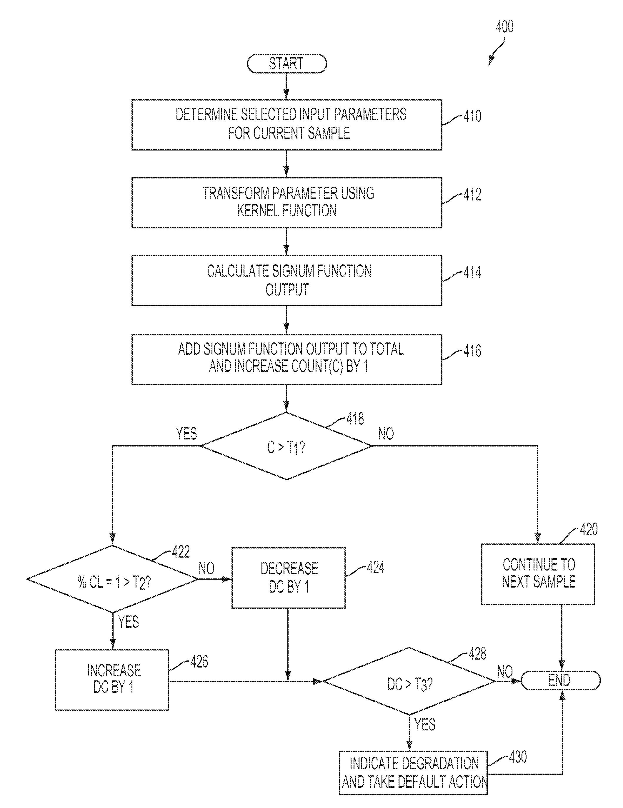
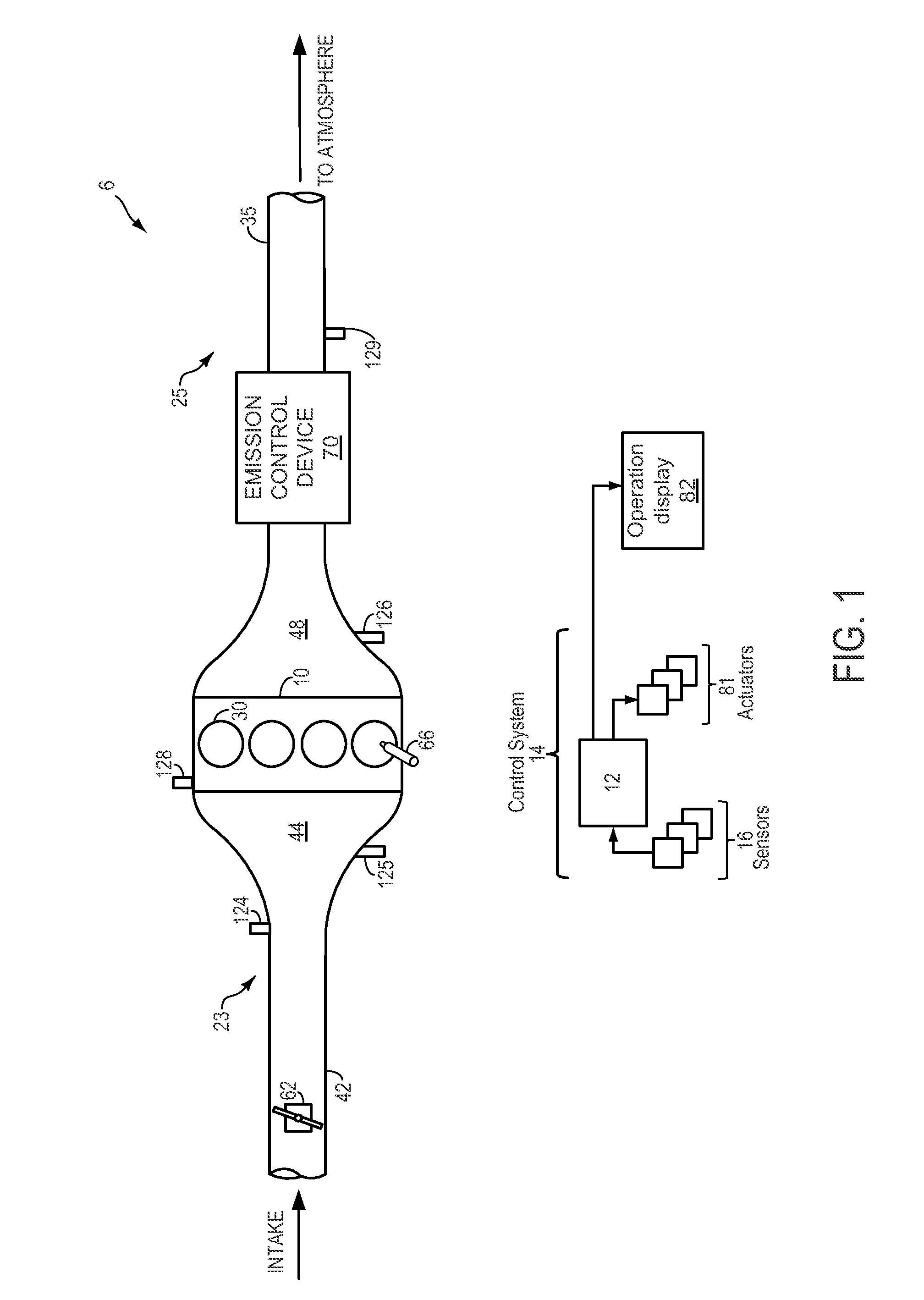
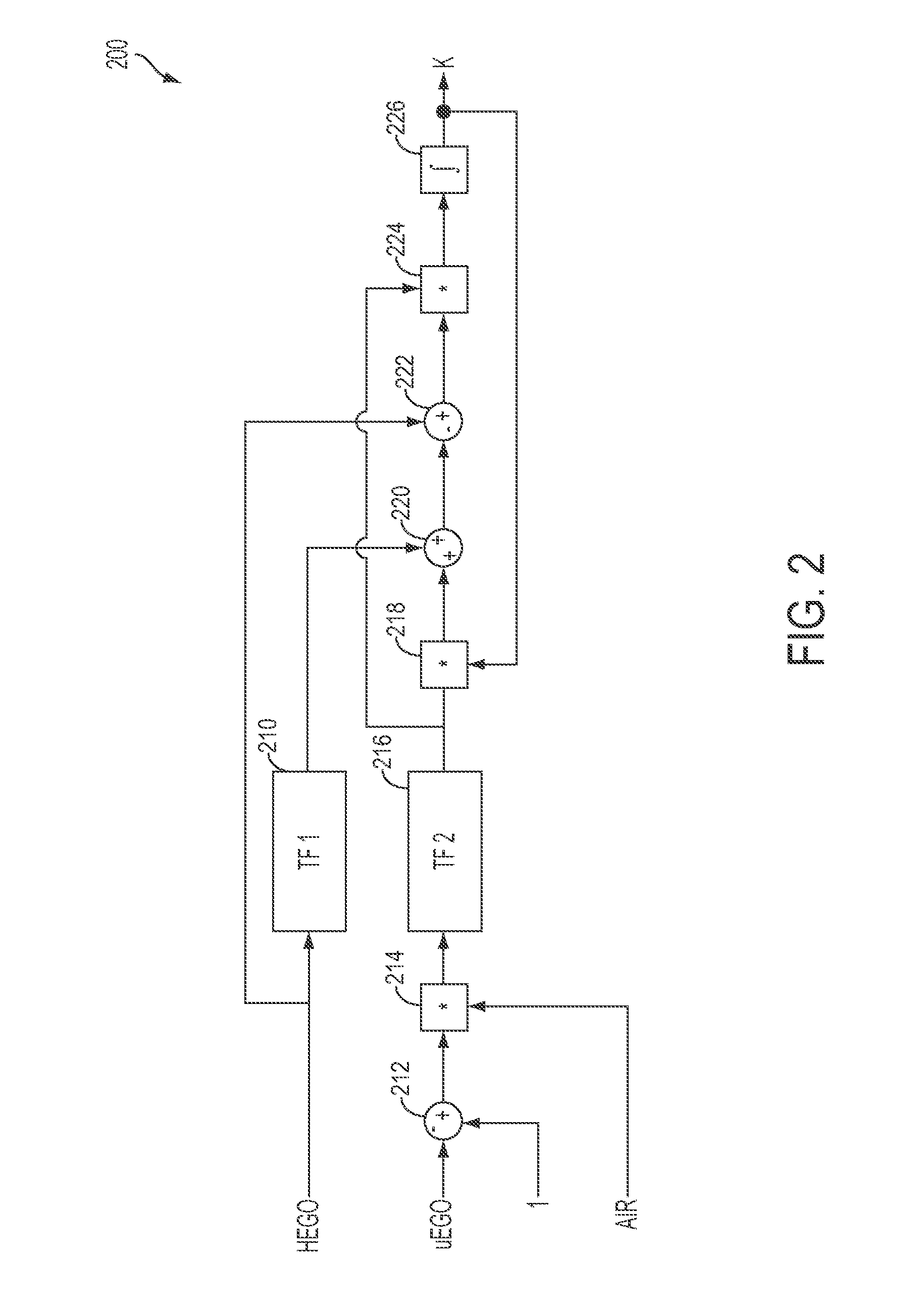
[0013]A support vector machine (SVM) may be used by a catalyst monitor to predict catalyst function. The SVM may be trained using pre-classified, known input parameters. During operation of a vehicle under selected conditions, various unclassified input parameters may be fed into the trained SVM model, and after a pre-defined number of samples have been classified, the total of each classification may be compared to a threshold to determine whether or not the catalyst is functioning. As example vehicle system including a catalyst is depicted in FIG. 1. Example control routines for determining an input parameter and operating the catalyst monitor are shown in FIGS. 2-4.

[0014]FIG. 1 shows a schematic depiction of a vehicle system 6. The vehicle system 6 includes an engine 10 having a plurality of cylinders 30. The engine 10 includes an intake 23 and an exhaust 25. The intake 23 includes a throttle 62 fluidly coupled to the engine intake manifold 44 via an intake passage 42. The exhaus...


PUM


Abstract

Embodiments for predicting catalyst function are disclosed. One example embodiment includes applying a set of parameter readings for a given sample to a support vector machine to generate a classification output, recording a plurality of classification outputs for a plurality of successive samples over a first duration, and indicating catalyst degradation if a threshold percentage of the classification outputs indicates degraded catalyst performance. In this way, catalyst degradation may be indicated using a simplified model that does not require extensive calibration.

Description

FIELD[0001]The present disclosure relates to monitoring a catalyst in a vehicle system.BACKGROUND AND SUMMARY[0002]Engine catalyst diagnostics may be used to determine whether a catalyst is sufficiently functioning to reduce exhaust gas emissions. Various approaches may be used to identify the catalyst system performance, such as model based approaches, fuzzy logic, etc.[0003]In the various approaches that have been used, there has often been a tradeoff in terms of the amount of “training” data needed, calibration required, and the level of diagnostic accuracy required (e.g., false positive, undetected degradation, etc.). Furthermore, these techniques have often required extensive windowing functions, where data from only selected operating conditions are considered, such as certain speed / load points, steady state operation, etc.[0004]The inventors herein have recognized the issues with the above approach and provide a method to at least partly address them. One example embodiment i...

Claims


Application Information

Patent Timeline
Patent Type & Authority Patents(United States)
IPC IPC(8): G01M15/10G06N20/10
CPCF01N11/00F01N2550/02G01N33/007G06N99/005Y02T10/47G06N20/00Y02T10/40G06N20/10
Inventor MAKKI, IMAD HASSANKERNS, JAMES MICHAELUHRICH, MICHAEL JAMESSMITH, STEPHEN B.KUMAR, PANKAJBANKER, ADAM
Owner FORD GLOBAL TECH LLC
Why Eureka
Try Eureka