Method and apparatus for a pressure measuring cell

a pressure measuring cell and pressure measurement technology, applied in the direction of fluid pressure measurement, manufacturing tools, instruments, etc., can solve the problems of high manufacturing cost, limited temperature range of use, and affect the function, so as to avoid the negative electrical effects of water molecules buildup, the effect of simple manufacturing

Active Publication Date: 2014-08-12
VEGA GRIESHABER GMBH & CO
View PDF4 Cites 1 Cited by
  • Summary
  • Abstract
  • Description
  • Claims
  • Application Information

AI Technical Summary

Benefits of technology

[0015]The problem in the art is solved by a pressure measuring cell with a protective layer inside it, so that the negative electrical effects from buildup of water molecules are largely avoided, is simple to manufacture, and the aforementioned drawbacks in regard to the protective layer are avoided.
[0019]Such a glass layer, passivating both the base body and also the membrane body, is resistant to high temperature, yet easy to produce, since its fabrication is done prior to the joining together of the base body with the membrane body into a complete measuring cell. Moreover, such a glass layer according to the invention achieves a good moisture protection and at the same time also a mechanical protection of the electrodes, since especially in an overload situation it prevents the electrodes from rubbing against each other and thereby prevents a loosening of particles from the electrodes.
[0020]According to one embodiment of the present invention, it is advantageous to cover with the glass layer the entire surface of the base body on which the at least one base body electrode is formed, and preferably in identical manner also the entire surface of the membrane body on which the membrane electrode is formed.
[0021]This substantially simplifies the fabrication process for depositing the glass layer onto the surfaces of the base body and the membrane body that are provided with the electrodes, since no structuring of these surfaces is required for this.
[0022]According to another embodiment of the present invention, it is advantageous for the base body and the membrane body to be joined together at the margin by means of a spacing holder produced as glass solder. Joining of the base body and the membrane body by means of the glass solder produces a complete glass encapsulation in the interior of the measurement cell.
[0026]The method of the present invention further provides for receiving an electronic signal from the at least one membrane electrode upon subjection to the pressure of the medium, thereby enabling an operative measuring of the metered pressure.

Problems solved by technology

Due to the supplying of the reference air through the vent opening, moisture gets into the sensor chamber, and when it drops below its dew point it may condense there and impair the function.
Since such coatings of silanes are organic, they have a limited temperature range of use.
A further drawback is that such coatings on account of the temperature limitations can only be created after the joining of membrane and base body by means of a vacuum through the vent opening in the base body, i.e., a high manufacturing expense is required for this.
Since this is likewise a vacuum method, the expense is very large and the result of a uniform layer deposition can only be checked with difficulty.
Furthermore, the resulting layers of silane compounds are likewise not resistant to high temperature.
What is not appreciated by the prior art are the costs associated from protecting the sensor chambers of pressure measuring cells from the negative electrical effects from the buildup of water molecules within those chambers.

Method used


Image

  • Method and apparatus for a pressure measuring cell
  • Method and apparatus for a pressure measuring cell

Examples


Embodiment Construction

[0033]Reference will now be made in detail to several embodiments of the invention that are illustrated in the accompanying drawings. Wherever possible, same or similar reference numerals are used in the drawings and the description to refer to the same or like parts or steps. The drawings are in simplified form and are not to precise scale. For purposes of convenience and clarity only, directional terms, such as top, bottom, up, down, over, above, and below may be used with respect to the drawings. These and similar directional terms should not be construed to limit the scope of the invention in any manner. The words “connect,”“couple,” and similar terms with their inflectional morphemes do not necessarily denote direct and immediate connections, but also include connections through mediate elements or devices.

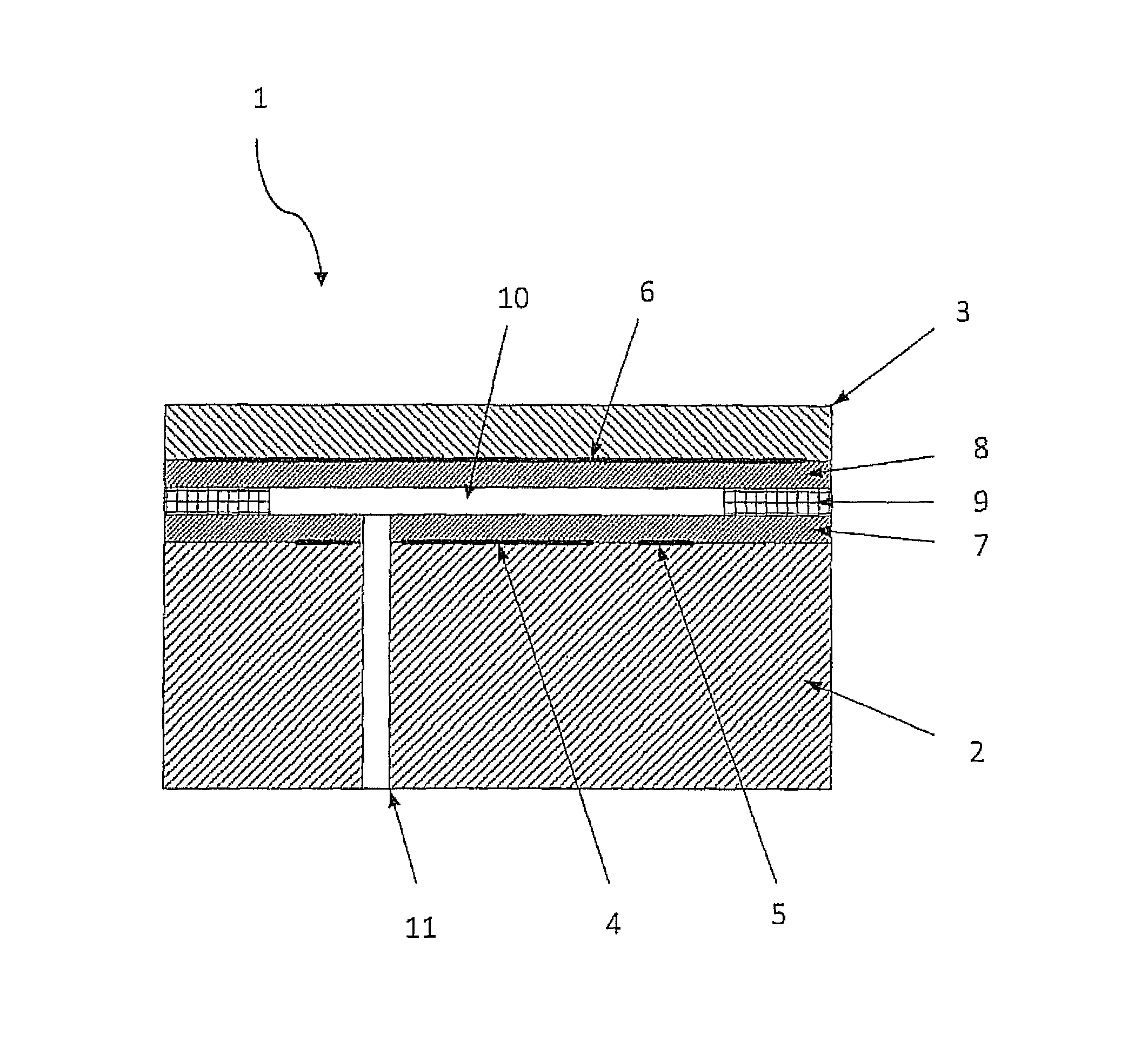
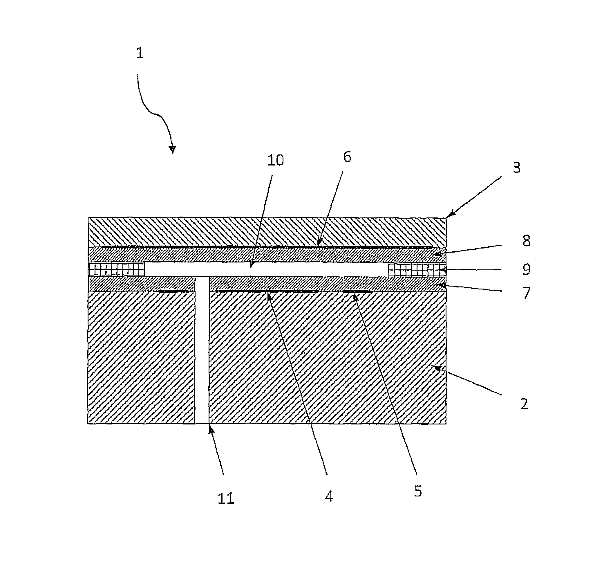
[0034]Turning to FIG. 1, the relative pressure measuring cell 1 represented is designed as a ceramic capacitive pressure sensor. One example of the ceramic material that can ...


PUM

PropertyMeasurementUnit
pressureaaaaaaaaaa
pressure sensorsaaaaaaaaaa
relative pressureaaaaaaaaaa

Abstract

The invention is for a method and apparatus for a pressure measuring cell for measuring a metered pressure, with a base body having at least one base body electrode and with a membrane body connected to the base body to form a sensor chamber, which has at least one membrane electrode and can be subjected to the pressure of a medium that is below the measurement pressure, wherein both the wall of the sensor chamber that is formed by the base body and the wall of the sensor chamber that is formed by the membrane body is covered with a protective layer; according to the invention, the protective layer is fashioned as a glass layer.

Description

CROSS REFERENCE TO RELATED APPLICATIONS[0001]This application relates to, and claims priority from, European Patent Application Ser. No. 10 015 383.2, filed Dec. 7, 2010, the entire contents of which is incorporated herein fully by reference.[0002]Further, this application is related to U.S. Provisional Application Ser. No. 61 / 421,142, filed Dec. 7, 2010, the entire contents of which is incorporated herein fully by referenceFIGURE FOR PUBLICATION[0003]FIG. 1.BACKGROUND OF THE INVENTION[0004]1. Field of the Invention[0005]The present invention relates to a method and apparatus for a pressure measuring cell. More specifically, the present invention relates to a relative pressure measuring cell for measuring a pressure and having a base body with at least one base body electrode and with a membrane body connected to the base body to form a sensor chamber.[0006]2. Description of the Related Art[0007]The related art involves relative pressure sensors which are used to measure the differe...

Claims


Application Information

Patent Timeline
Patent Type & Authority Patents(United States)
IPC IPC(8): G01L7/00G01L9/00
CPCG01L9/0072Y10T29/49826
Inventor KOPP, THOMASJACOB, JORNMELLERT, MARTINFEHRENBACH, JOSEFDECK, THOMAS
Owner VEGA GRIESHABER GMBH & CO
Why Eureka
Try Eureka