Inflatable watercraft with reinforced panels

a technology of reinforced panels and inflatable watercraft, which is applied in the field of inflatable watercrafts, can solve the problems of large storage volume, limited quantity available for multiple rib deployment from hosts, and large stowage volume of conventional rigid inflatable boats (ribs)

Active Publication Date: 2014-08-12
HULL SCI RES LLC
View PDF83 Cites 21 Cited by
  • Summary
  • Abstract
  • Description
  • Claims
  • Application Information

AI Technical Summary

Problems solved by technology

Conventional rigid (hull) inflatable boats (RIBs) typically lack an advantage of inflatable watercrafts, in that the former are not foldable, collapsible, or rollable into a compact storage configuration.
Instead, these conventional RIBs have large stowage volumes that limit the quantities available for multiple RIB deployment from hosts, such as ships, aircraft and land transports.
Although the inflatable tubes on these RIBs can be deflated and stored in a smaller volume, the stowage footprint of the remainder of the hull cannot be significantly reduced by conventional manufacturing techniques.
While conventional inflatable boats (IBs), on the other hand, benefit from reduced stowage footprints; they, however, suffer from the drawback of not being rigid enough even when fully inflated.
Instead, the entire boat can bend and deflect to uncomfortable amounts in various seaways.
Additionally, with the use of conventional inflatable materials in such IBs, the required stiffness and definition in structure cannot be achieved so as to assemble a fully inflatable boat with hydrodynamic features and structures of the counterpart rigid boat, one example of such feature and structure being running strakes along the hull form.

Method used


Image

  • Inflatable watercraft with reinforced panels
  • Inflatable watercraft with reinforced panels
  • Inflatable watercraft with reinforced panels

Examples


Embodiment Construction

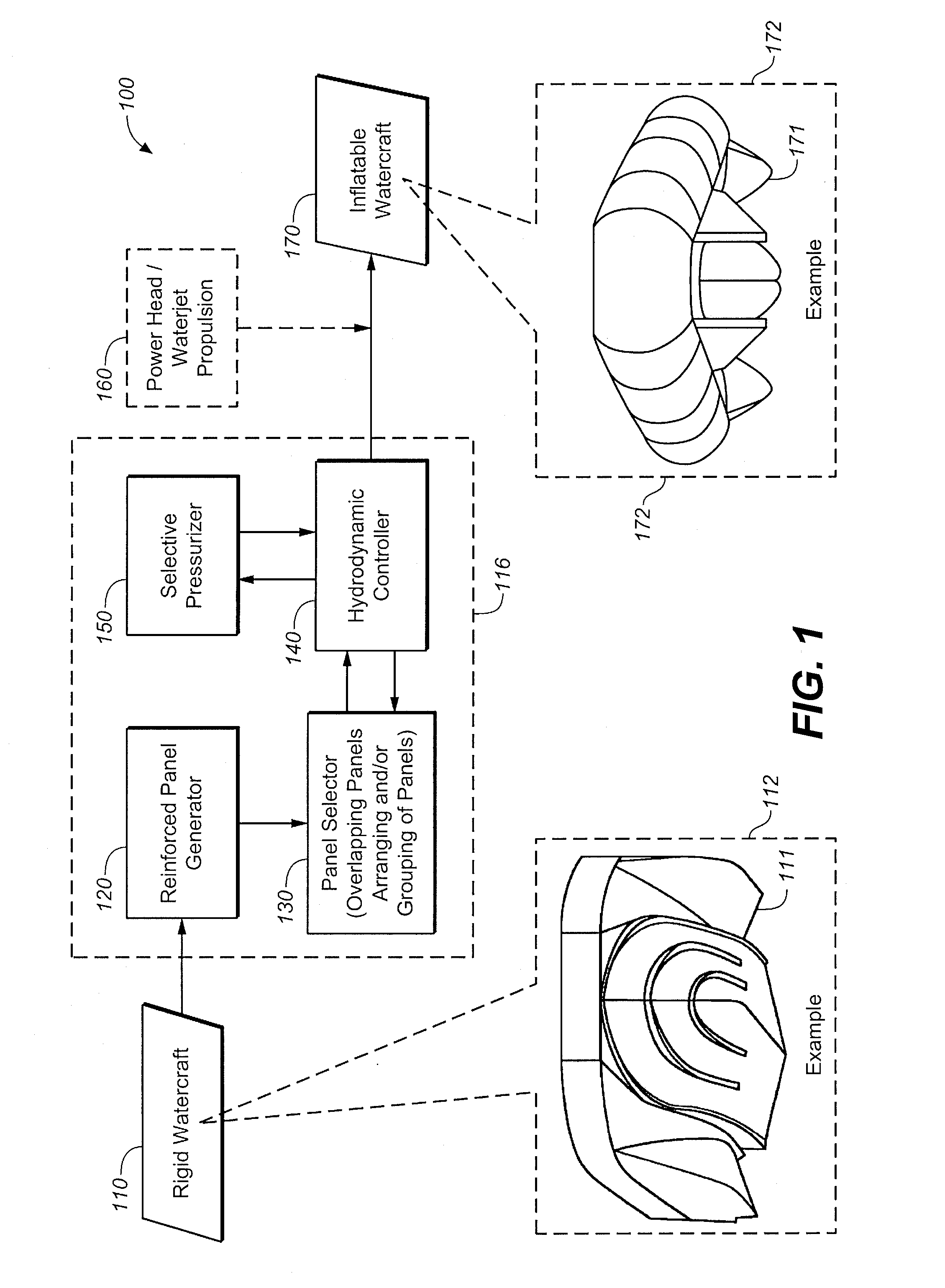
[0030]Referring now to the drawings in detail, FIG. 1 illustrates a functional block diagram of an example of a system for assembling an inflatable watercraft with reinforced panels, according to at least some embodiments of the invention. As shown, diagram 100 includes input parameters 110 of a rigid watercraft, a system for designing, assembling and manufacturing an inflatable watercraft with reinforced panels 116, power head / waterjet propulsion module 160, and output inflatable watercraft parameters 170. Input parameters 110 of a rigid watercraft is an entrapment tunnel monohull vessel 111 depicted in the callout 112, by way of example. One known rigid entrapment monohull (ETM) vessel 111 is found in U.S. Pat. No. 7,418,915, by Lorne F. Campbell, entitled “Entrapment Tunnel Monohull Optimized Waterjet and High Payload”, issued Sep. 2, 2008, the subject matter of which is hereby incorporated by reference in its entirety.

[0031]System 116 includes a reinforced panel generator 120, a...


PUM


Abstract

An inflatable watercraft is provided with multiple reinforced panels that are configured to form a center hull having a V-form. The center hull supports a floor that is coupled to a U-form collar. The panels also form a pair of outer side hulls respectively disposed on opposite sides of the center hull and which define a tunnel between the center hull and each of the outer side hulls.

Description

CROSS REFERENCE TO RELATED APPLICATION[0001]This application claims priority to 35 U.S.C. §119(e) from co-pending and commonly-assigned U.S. Provisional Application No. 61 / 357,946, filed on Jun. 23, 2010 by Gary Shimozono, et al., entitled “Entrapment Watercraft with Inflatable Drop Stitch,” and U.S. Provisional Application No. 61 / 442,171, filed on Feb. 11, 2011 by Steven C. H. Loui, et al., entitled “Watercraft with Airbeams,” the subject matter of both are fully incorporated by reference herein in their entireties.GOVERNMENT LICENSE RIGHTS[0002]This invention may have been made with Government support under Cooperative Agreement HR0011-07-2-005 awarded by the Defense Advanced Research Projects Agency. The Government may have certain rights in the invention, which may include a paid-up license in this invention and right in limited circumstances to require the patent owner to license others on reasonable terms.BACKGROUND OF THE INVENTION[0003]1. Field of the Invention[0004]The pres...

Claims


Application Information

Patent Timeline
Patent Type & Authority Patents(United States)
IPC IPC(8): B63B7/00
CPCB63B7/00B63B7/082B63B1/22B63B39/10B63B2001/201B63B2001/203B63B2039/105
Inventor SHIMOZONO, GARYYAMASHITA, SCOTTLOUI, STEVEN C. H.SCHIFF, ERICKLINE, JEFFHART, CHRISTOPHER J.
Owner HULL SCI RES LLC
Why Eureka
Try Eureka