Clamping device

a technology of sling and clamping device, which is applied in the direction of load-engaging elements, haberdashery, etc., can solve the problems of presenting a hazard to workers, slings no longer under as much tension, and slings that are no longer held in relatively taut sling configurations, so as to reduce the damage to the first rope portion, reduce the amount of wear, and smooth the surface

Active Publication Date: 2014-08-12
CLAMPSAFE INT
View PDF12 Cites 4 Cited by
  • Summary
  • Abstract
  • Description
  • Claims
  • Application Information

AI Technical Summary

Benefits of technology

[0011]Embodiments of a clamping device wherein the fastening member comprises a bolt and a tightening nut provide the advantage of allowing the clamping member to be gradually loosened from and tightened with the first rope portion so that, when the clamping device is used to retain the rope portions in a sling configuration suitable for lifting a bundle of pipes or the like, the clamping device may be gradually engaged with the first rope portion when the sling configuration is relatively taut, and similarly gradually disengaged when the load has been set down so that the sling configuration does not lose tension immediately.
[0012]Embodiments of the clamping device with the fastening member may allow the clamping device to be clamped onto the first rope portion to retain the second rope portion, and correspondingly unclamped from the first rope portion by one operator.
[0016]Engaging surfaces of the clamping portion for engaging with the first rope portion may be arranged so as to substantially reduce damage to the first rope portion when the clamping portion is engaged with and / or disengaged from the first rope portion, for example by having a substantially smooth surface.
[0017]Such engaging surfaces of the clamping portion provide the advantage of reducing the amount of wear to the first rope portion if other means were otherwise used. This is particularly useful when the clamping device is used on relatively expensive wire slings.
[0018]The retaining portion may be shaped so as to prevent the second rope portion from moving in such a way so as to reduce the tension on the sling configuration, for example by preventing the second rope portion from jumping over the first rope portion. In use, the second rope portion may be retained between the retaining portion and the first rope portion.
[0024]Providing a beveled cut-out may substantially reduce the ease with which the bolt may be accidentally disengaged from the second clamping member when the clamping portion is in the engaging configuration after the bolt has been swung into position so as to be received by the second clamping member.

Problems solved by technology

However, using such a sling configuration may present difficulties.
However, when the bundle is set down at a desired destination, the sling is no longer under as much tension and may no longer be held in the relatively taut sling configuration.
Accordingly, the pipes may be free to spill outwardly from the bundle, thereby presenting a hazard to workers.
However, such methods and devices have been relatively time consuming and have required at least two people to implement.
Not only is a method such as this time consuming, but removal of the marlin twine will usually be done by cutting the marlin twine from the junction which will cause the sling configuration to lose its relative tautness suddenly.
This can still lead to spillage of the load, thereby endangering the worker tasked with cutting the marlin twine.

Method used


Image

  • Clamping device
  • Clamping device
  • Clamping device

Examples


Embodiment Construction

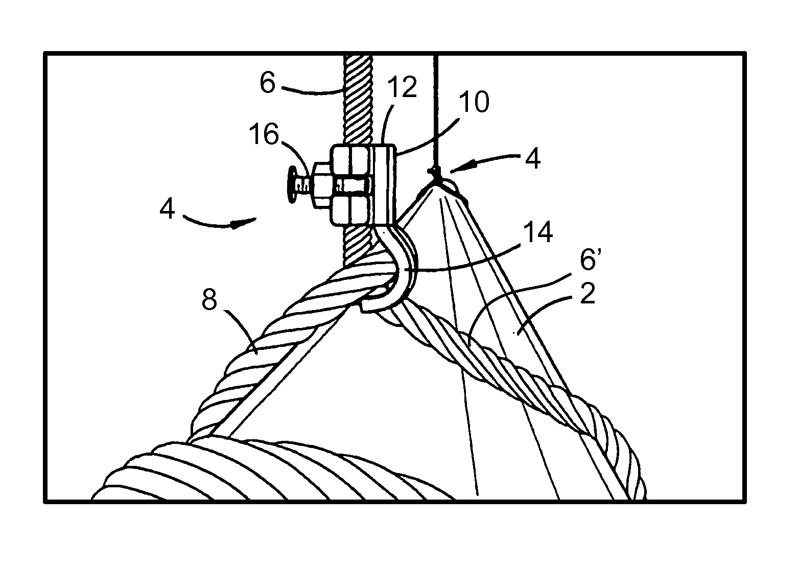
[0035]Embodiments of the present invention relate to a clamping device for clamping onto a first rope portion of a rope sling and retaining a second rope portion of the rope sling relative to the position of the first rope portion. This allows the clamping device to be used with a rope sling arranged in a sling configuration used to lift a bundle of pipes or casings, wherein the relative positions of the first and second rope portions of the rope sling are retained such that a relatively taut sling configuration is maintained when the bundle is delivered to a desired destination e.g. shore to rig or rig to shore. Such lifting methods are also commonly used on building or mining sites.

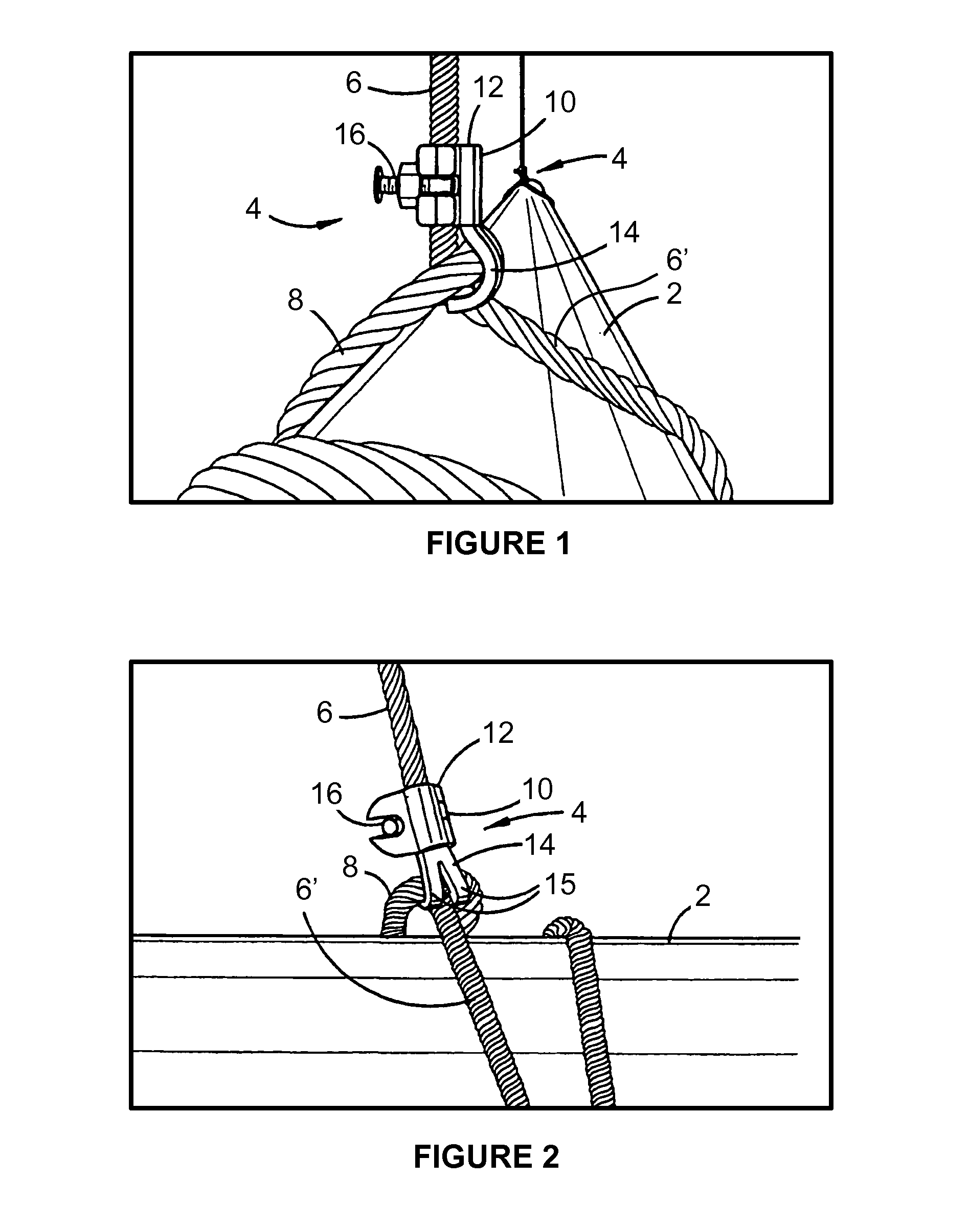
[0036]Such a clamping device is shown clamped to a first rope portion and retaining a second rope portion of a rope sling in FIG. 1. In particular, FIG. 1 shows a bundle of pipes 2 being lifted by a plurality of rope slings 4, the rope slings each comprising a first rope portion 6, a second rope portion...


PUM

PropertyMeasurementUnit
shapeaaaaaaaaaa
curved shapeaaaaaaaaaa
tensionaaaaaaaaaa

Abstract

A safety clamping device for clamping onto a first rope portion and retaining a second rope portion. The clamping device comprises a clamping portion and a retaining portion. The clamping portion clamps onto the first rope portion, and comprises first and second clamping members in use hingedly coupled to one another such that the clamping portion is movable between an open configuration suitable for receiving the first rope portion and a clamping configuration suitable for clamping onto the first rope portion. The retaining portion retains the second rope portion relative to the position of the first rope portion, and is coupled to the clamping portion.

Description

FIELD OF THE INVENTION[0001]The present invention relates to a clamping device. In particular, although not exclusively, the present invention relates to a sling safety clamping device.BACKGROUND OF THE INVENTION[0002]A load, such as a bundle of casing pipes, may be transported by means of a wire rope arranged in a sling configuration. However, using such a sling configuration may present difficulties. For example, as the load is lifted, the sling configuration becomes relatively taut under the applied tension. However, when the bundle is set down at a desired destination, the sling is no longer under as much tension and may no longer be held in the relatively taut sling configuration. Accordingly, the pipes may be free to spill outwardly from the bundle, thereby presenting a hazard to workers.[0003]Previous methods and devices have been used for retaining the sling in a relatively taut configuration after the load has been delivered. However, such methods and devices have been rela...

Claims


Application Information

Patent Timeline
Patent Type & Authority Patents(United States)
IPC IPC(8): B66C1/34B66C1/14B66C1/12
CPCB66C1/12B66C1/14Y10T24/3956
Inventor MANSFIELD, BRADLEY ERNESTMANSFIELD, PETER FREDERICK
Owner CLAMPSAFE INT
Why Eureka
Try Eureka