
Distributed call routing in a VoIP system

a technology of distributed call routing and voip system, which is applied in the field of voice over internet protocol (voip) technology, can solve the problems of slow and unreliable call setup, centralized routing system failure to take advantage of more sophisticated, and impracticality of centralized routing decisions

Inactive Publication Date: 2014-08-12
OOMA
View PDF12 Cites 19 Cited by
  • Summary
  • Abstract
  • Description
  • Claims
  • Application Information

AI Technical Summary

Benefits of technology

The invention aims to improve the quality and efficiency of calls made over the PSTN network. It does this by separating the codec technology used by the ATAs (which are more advanced but slower in terms of their rate of evolution) from that used by the termination gateways (which are less advanced but are more widely used). This allows the best possible bandwidth efficiency and voice quality to be maintained from the subscriber's ATA through the VoIP service operator's network and the PSTN. The invention also provides a distributed network routing architecture that is able to handle the rapid evolution of codec technology, is flexible, and can efficiently traverse routers and security firewalls to provide an easy plug-and-play experience for the end user.

Problems solved by technology

This centralized call routing can lead to slow and unreliable call setup and possible problems stemming from race conditions related to the latency between the time it takes centralized processing elements to detect conditions which may affect call routing and the time it takes to communicate routing decisions out to the elements of the network such as the ATAs and termination gateways which actually carry the call connection.
Such centralized routing systems fail to take advantage of more sophisticated ATAs which may perform functions beyond telephony and for which it is impractical to have all routing decisions centralized.
However, unless all network elements support these new codecs, they cannot be fully exploited by VoIP systems.
For example, the G.711 standard (ITU-T G.711) codec has commonly been used as a codec in VoIP systems, but the usual usage of that codec in VoIP systems does a poor job of handling lost or late packets (a common occurrence in packet networks) and consumes more bandwidth as compared to linear predictive codecs like iLBC, G.726 or G.729.

Method used


Image

  • Distributed call routing in a VoIP system
  • Distributed call routing in a VoIP system
  • Distributed call routing in a VoIP system

Examples


Embodiment Construction

Overview of System Architecture

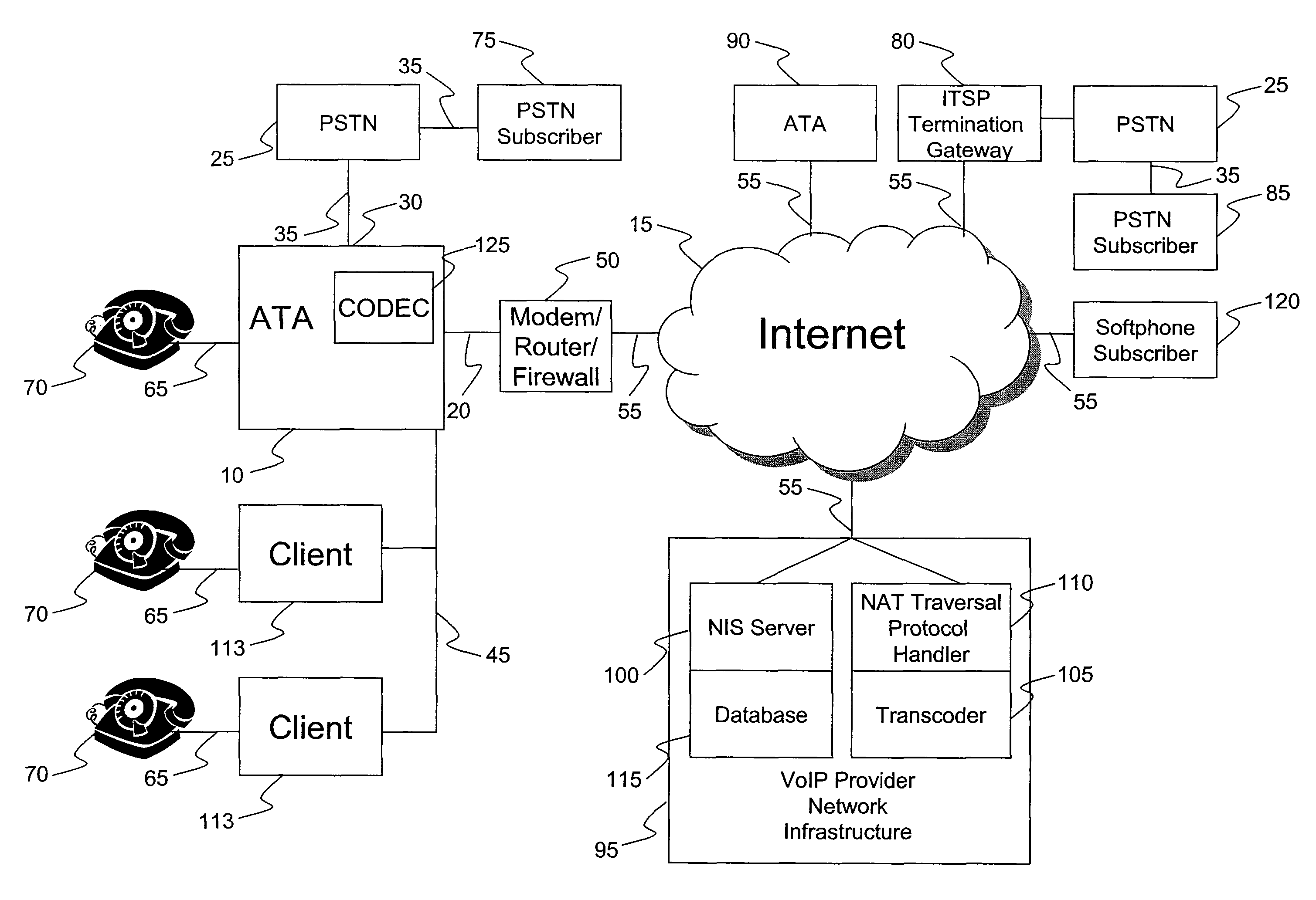
[0024]FIG. 1 is a block diagram showing the major system elements and interconnects in an embodiment of the present invention. In brief, embodiments of the present invention provide distributed intelligent routing for calls initiated by an ATA 10, which is located at a subscriber site. The subscriber may be referred to as a customer or user. Equipment at the subscriber site is often referred to in the industry as CPE (customer premises equipment). The ATA may place (and receive) calls over a broadband packet network 15 such as the Internet through a network connection 20, or possibly over the PSTN 25 through an optional foreign exchange office (FXO) port 30 connected to a landline 35. As will be discussed below, the ATA may also be connected to a number of client devices 40 over a subscriber-site (local area) network 45 (e.g., HPNA, Ethernet, DECT, wireless).

[0025]The VoIP subscriber connects ATA 10 to the network connection 20 connected through a mode...


PUM


Abstract

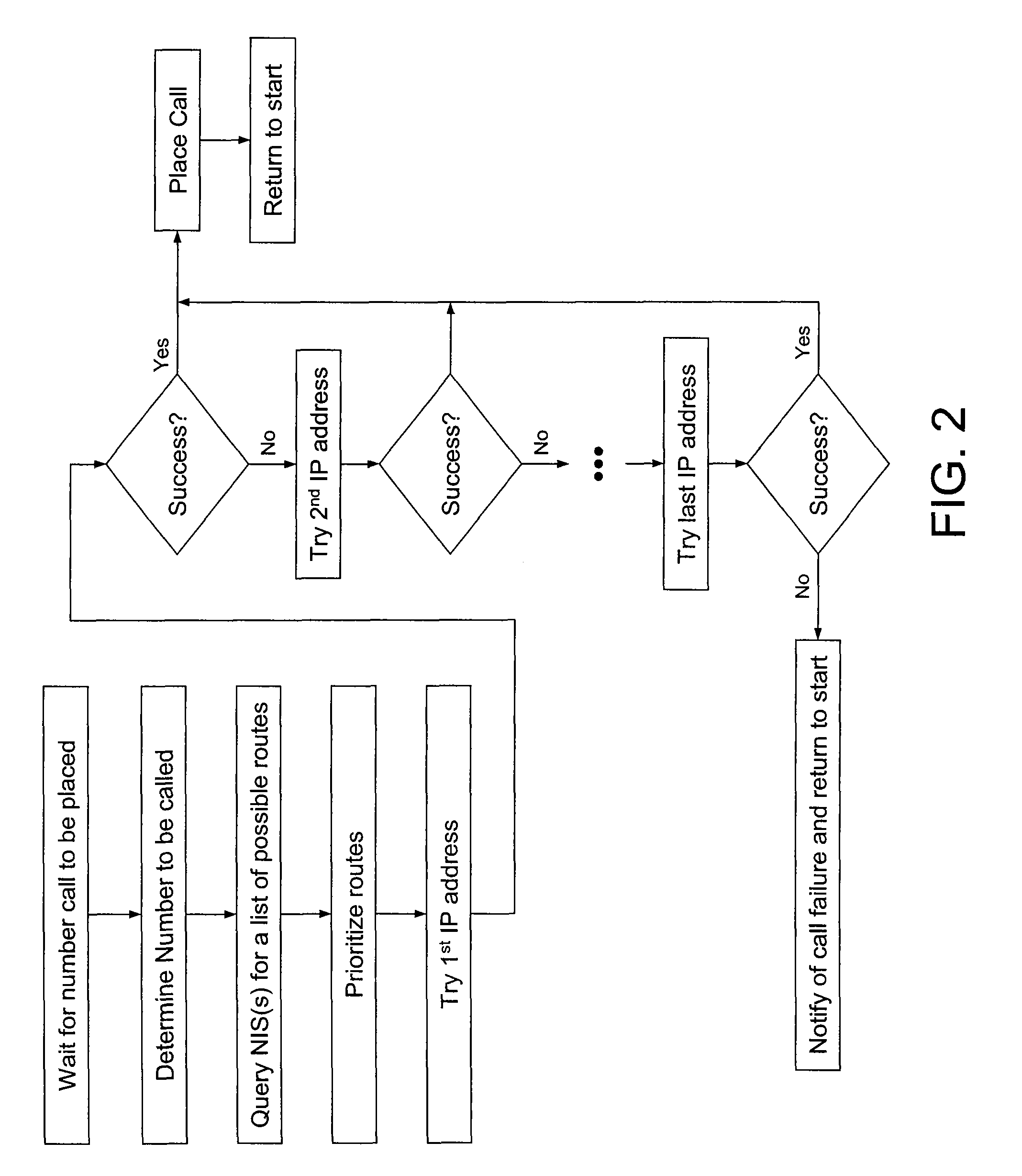
A distributed call routing system and method are used to provide higher quality VoIP connections with flexible codec choices and simplified NAT and firewall traversal. An analog telephone adapter (ATA) communicates a call destination to a network information server (NIS), which provides multiple routes. The ATA uses this information and local and / or non-NIS information to initiate the call using the preferred routing.

Description

BACKGROUND OF THE INVENTION[0001]This invention relates generally to voice over Internet protocol (VoIP) technology, and particularly to how call routing is performed to improve bandwidth efficiency, call quality, call setup time and call handling flexibility.[0002]In a public switched telephone network (PSTN), an initiating phone connects to a circuit switch and the PSTN via a first POTS (Plain Old Telephone System) line. A destination phone connects to the circuit switch and the PSTN via a second POTS line. The circuit switch electrically connects the initiating phone to the destination phone over the PSTN. The electrical connection is maintained for the entire duration of a phone call between the initiating phone and the destination phone. The electrical connection in the PSTN is commonly referred to as “circuit switched.”[0003]Voice over Internet protocol (VoIP) is a technology that permits phone calls to be carried over the Internet as opposed to over the PSTN. Being packet swi...

Claims


Application Information

Patent Timeline
Patent Type & Authority Patents(United States)
IPC IPC(8): H04L12/66H04L29/06
CPCH04L65/1069H04L65/1026H04L65/00H04L65/103H04L45/00H04L61/2514H04L61/2564H04L61/2575H04L61/2592H04L63/0272H04L63/029H04M7/1285H04M7/0006
Inventor CAPPER, SIMONCHEUNG, KELVIN LEONARD
Owner OOMA
Learn More