Cab suspension system for an off-road vehicle

a suspension system and off-road vehicle technology, applied in the field of off-highway vehicles, can solve the problems of reducing the productivity of the operator, not reducing the amplitude of the jolt, and providing little isolation of frequencies such as those seen on tracked vehicles, so as to improve the ride comfort and the associated productivity of the vehicle operator, the effect of reducing road vibration

Active Publication Date: 2014-08-19
BLUE LEAF I P INC
View PDF34 Cites 19 Cited by
  • Summary
  • Abstract
  • Description
  • Claims
  • Application Information

AI Technical Summary

Benefits of technology

[0006]The present invention provides a novel system and method for mounting a cab on an off-road vehicle designed to respond to such needs. The inventive arrangements provide for suspension of the cab superstructure on the frame or chassis of the vehicle. The design provides substantial improvements in ride comfort and associated productivity of the vehicle operator by reducing road vibration transmitted to the cab from tire lugs or tracks, while absorbing sudden jolts as the vehicle moves over rough terrain. It can be adapted to various sizes, weights and configurations of cabs and vehicle structures, supporting, in certain currently contemplated embodiments 2000 pound (900 Kg) cabs.

Problems solved by technology

This type of mounting does provide some reduction in noise and vibration transmission from the chassis during vehicle operation, but do not mitigate higher amplitude jolts and provide little isolation of frequencies such as those seen on tracked vehicles.
Over a typical work period of several or many hours, resulting noise and vibration fatigue the operator and ultimately reduce his or her productivity.

Method used


Image

  • Cab suspension system for an off-road vehicle
  • Cab suspension system for an off-road vehicle
  • Cab suspension system for an off-road vehicle

Examples


Embodiment Construction

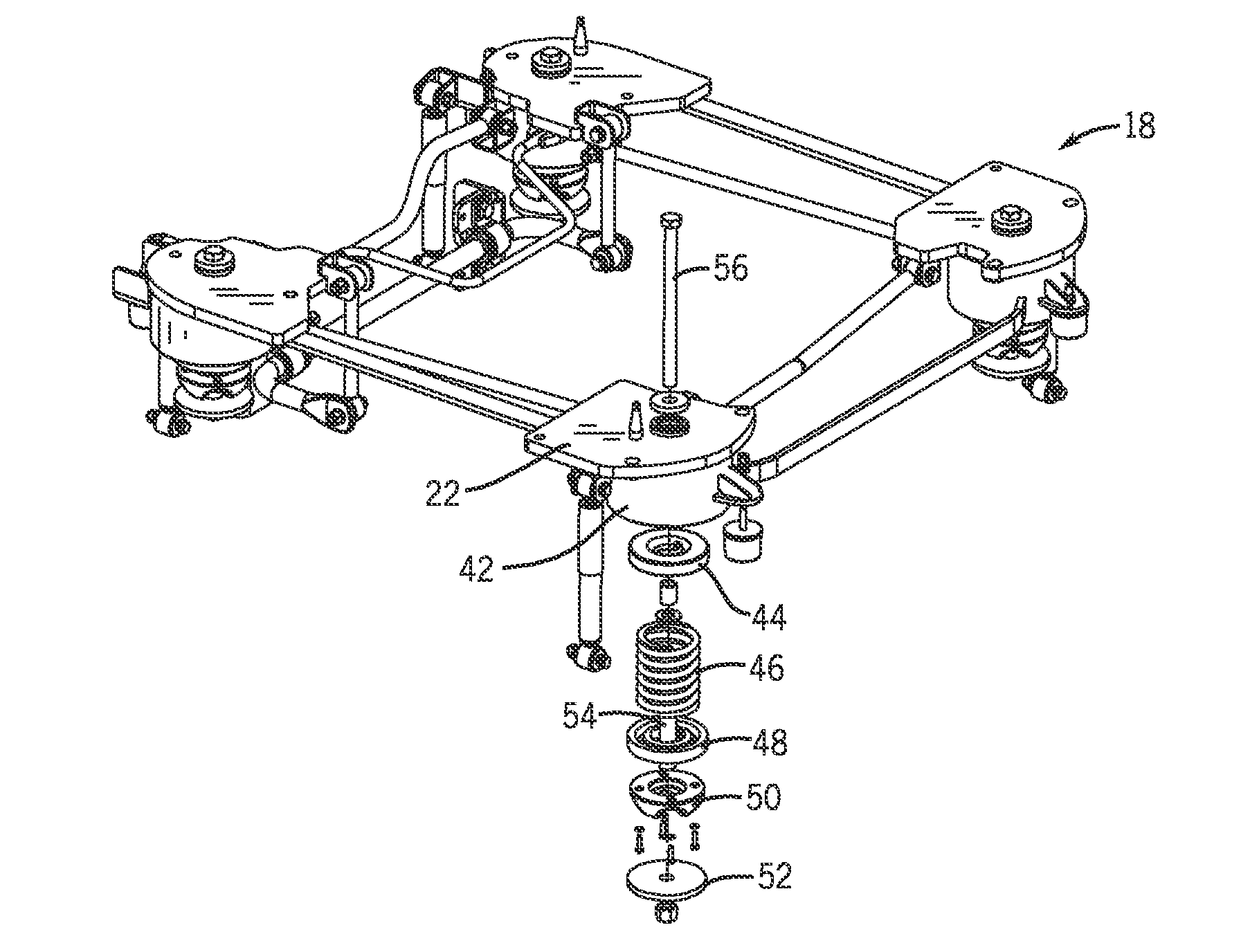
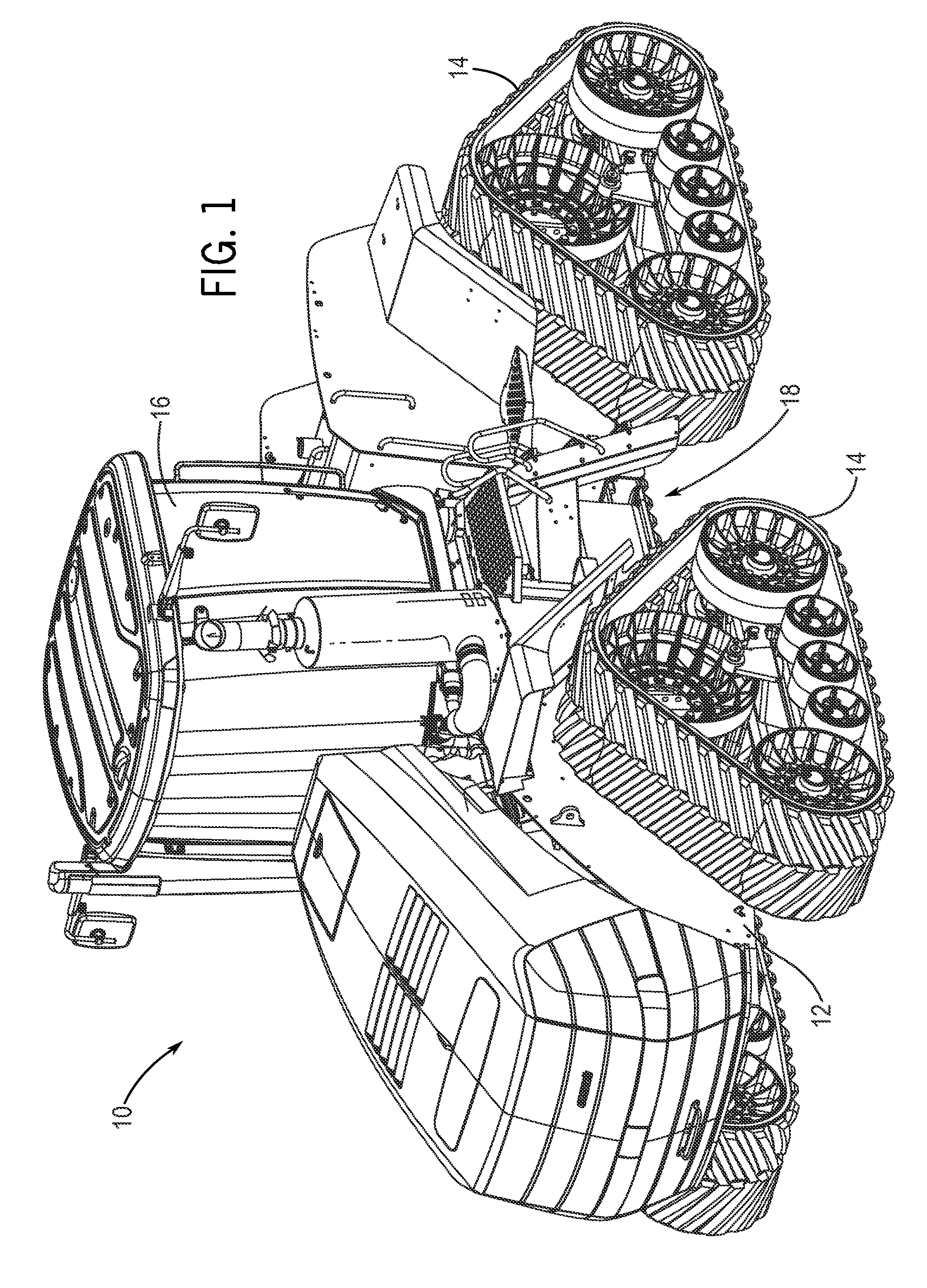
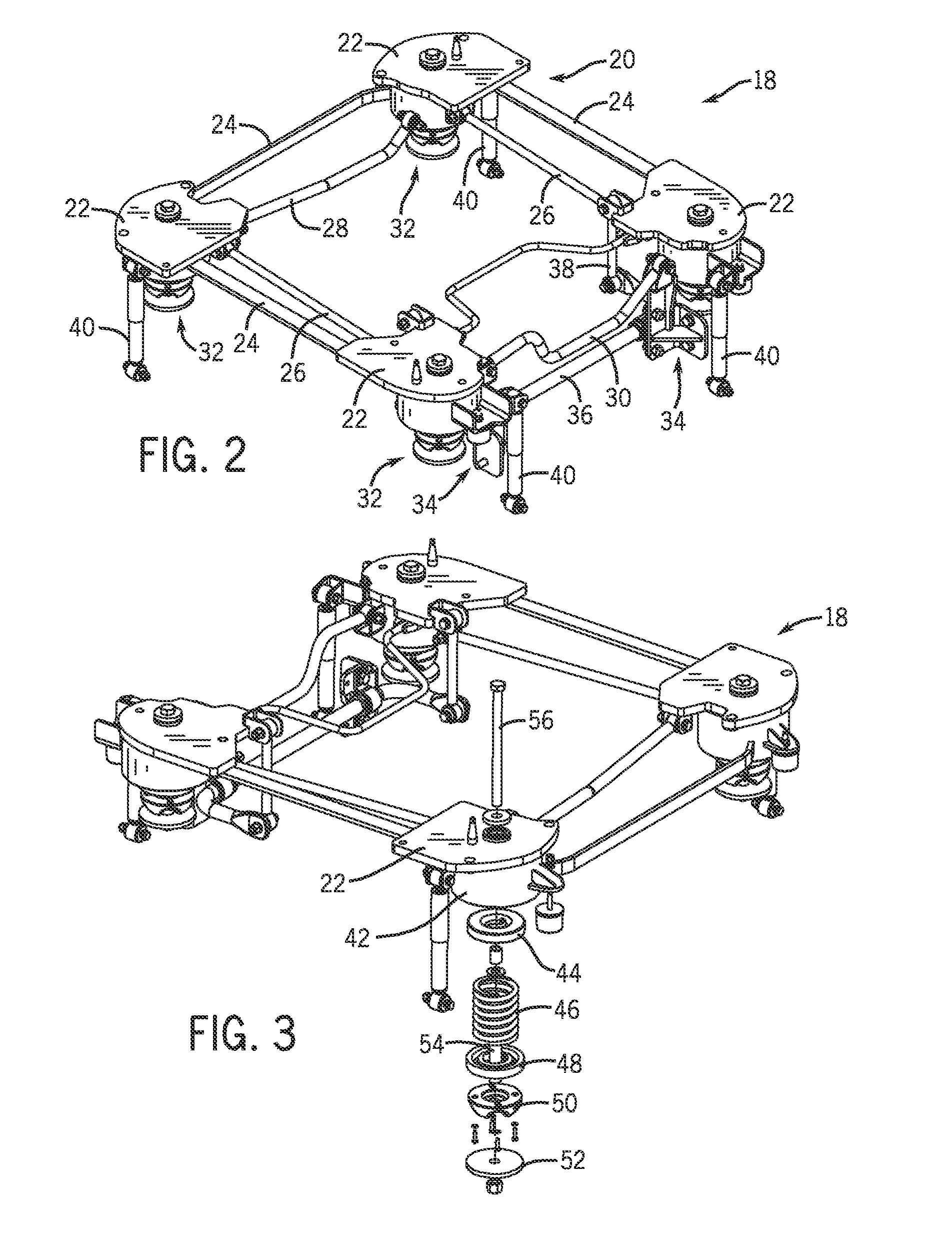
[0015]The following discussion describes an exemplary embodiment of the inventive cab suspension system as it might be used on a work vehicle, tractor, combine, or any other off-road vehicle. The field of off-road vehicles is somewhat unique insomuch as suspension systems must allow for both road travel at acceptable speeds, as well as transport over extremely rough terrain, such as in plowed fields, undeveloped lands, worksites and so forth. The design utilizes a four-link system, including rubber isolators and bumpers, springs, dampers, and a torsion bar, for various ride improvement components that combine to absorb normal operating shocks, while gradually increasing resistance to provide soft end of motion.

[0016]In the presently contemplated design described below, springs captured by rubber end caps are mounted vertically in four corners of the system. These allow for spring force control of loading during normal operating vertical motion with isolation of noise and vibration. ...


PUM

PropertyMeasurementUnit
weightsaaaaaaaaaa
travel resistanceaaaaaaaaaa
frequenciesaaaaaaaaaa

Abstract

A suspension system for a cab of an off-road vehicle includes a superstructure configured to receive a cab frame. The superstructure forms a framework, the corners of which receive suspension assemblies and dampers. The suspension assemblies include one or more springs or resilient elements to resist suspension motion, and the dampers provide dampening of the motion. Lateral and longitudinal suspension motions are resisted by links between the corners of the superstructure. An anti-roll bar reduces roll. The entire suspension system may be pre-assembled and then joined to the vehicle chassis frame. The cab frame may then be placed on the suspension system. Parts of the suspension system may interface with and be housed by roll-over protective structures.

Description

CROSS REFERENCE TO RELATED APPLICATIONS[0001]This application is a Non provisional Patent Application of U.S. Provisional Patent Application No. 61 / 499,549, entitled “Cab Suspension System for an Off-Road Vehicle”, filed Jun. 21, 2011, which is herein incorporated by reference.BACKGROUND[0002]The invention relates generally to off-highway vehicles, such as tractors, and more particularly to techniques for mounting operator cabs on such vehicles.[0003]A wide range of off-highway vehicles have been developed for various purposes. In simple vehicles, seats and other operator supports may be sufficient, and these may be mounted on various forms of springs and other suspension components. However, in larger or more complex vehicles, such as tractors, a partially or fully enclosed cab is more desirable, providing one or more operators with a comfortable location from which the vehicle may be transported and used for work purposes for hours on end. Such cabs, sometimes referred to as “oper...

Claims


Application Information

Patent Timeline
Patent Type & Authority Patents(United States)
IPC IPC(8): B60R21/13B62D33/06B62D33/077
CPCB62D33/0617B62D33/0604B60R21/131B62D55/065Y10T29/49622
Inventor MILBURN, ROWLAND JAMESBAKKEN, MICHAELVIRGILIO, SALVATORETVEITO, DAVID LARRYBOOTH, DAVID SHELDONRASSET, JOHN THOMASNOVACEK, JASON KEITHJORGENSON, DALLAS LEEBAUTZ, CHAD ALRYBUNNELL, MICHAELSCOTT, SHANE MICHAELZURN, DANIEL JOHNSTOLTMAN, RUSSELL
Owner BLUE LEAF I P INC
Why Eureka
Try Eureka