Surge-proof interface circuit

a technology of interface circuit and shielding circuit, which is applied in the direction of telephonic communication, light sources, light sources, etc., can solve the problems of insufficient suppression of breakover, difficult, and destruction of interface circuit, and achieve adequate current gain and high dielectric strength

Inactive Publication Date: 2014-08-19
TRIDONIC
View PDF10 Cites 6 Cited by
  • Summary
  • Abstract
  • Description
  • Claims
  • Application Information

AI Technical Summary

Benefits of technology

[0015]A core concept of the present invention consists in creating a surge-proof interface circuit with the aid of a Darlington circuit, wherein a high dielectric strength can be achieved in a relatively simple manner in relation to circuits by using surge-proof transistors, the price of which is better compared with a thyristor and which can also have adequate current gain, in order to provide for certain signal levels at an input of the interface circuit in dependence on a drive signal.

Problems solved by technology

These burst pulses can easily also lead to a destruction of the interface circuit if no protective circuit such as, for example, a filter circuit is provided.
However, this can be more difficult in the case of the surge pulses.
Although this turning-on or breakover of the thyristor can be influenced somewhat by circuit measures by connecting, for example, a capacitor directly from the gate to the cathode of the thyristor, the breakover can often not be adequately suppressed.

Method used


Image

  • Surge-proof interface circuit
  • Surge-proof interface circuit
  • Surge-proof interface circuit

Examples


Embodiment Construction

[0024]With respect to the following description of the exemplary embodiments of the present invention, it should be noted that, in the different figures, the same reference symbols are used for functionally identical or identically acting or functionally equal equivalent elements or steps for the purpose of simplification in the entire description. These elements having the same reference symbols are thus interchangeable with one another in the various exemplary embodiments.

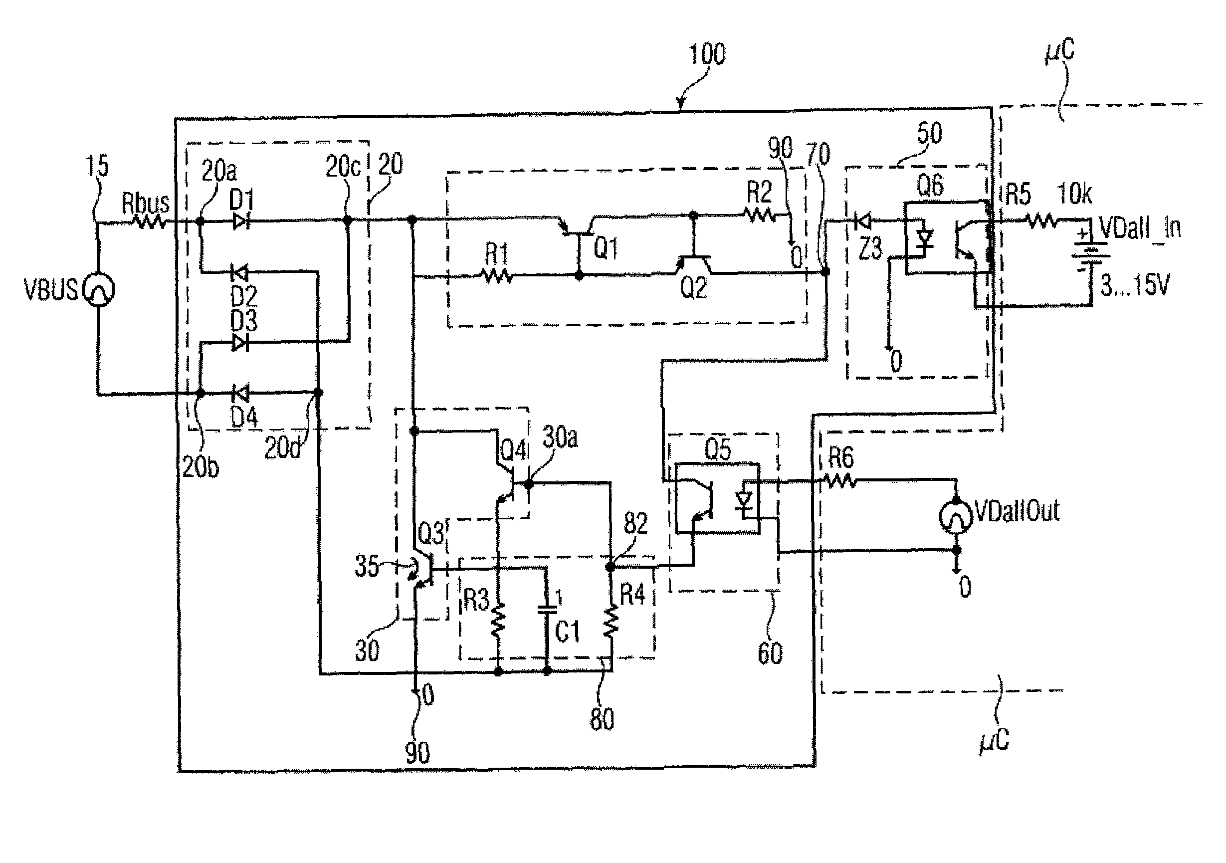
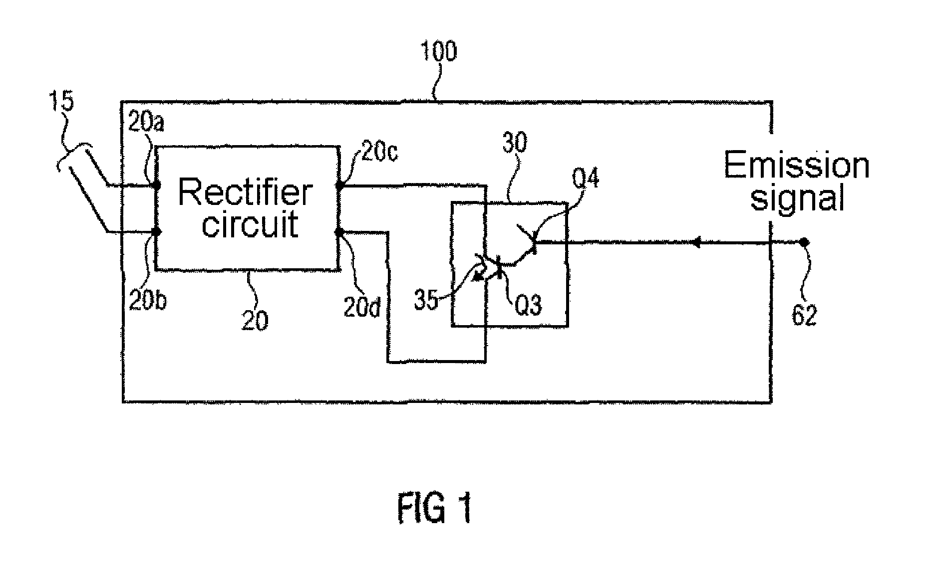
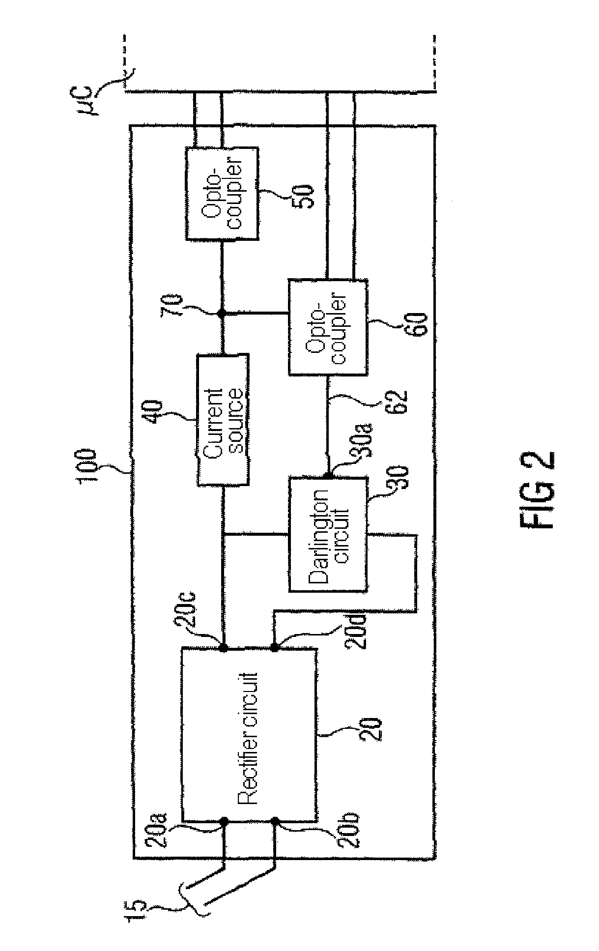
[0025]FIG. 1 shows a schematic block diagram of a surge-proof interface circuit 100 according to one exemplary embodiment of the present invention. The surge-proof interface circuit 100 has a rectifier circuit 20 which is designed for providing, in dependence on a rectifier input voltage present at rectifier input terminals 20a, 20b, a rectified rectifier output voltage at rectifier terminals 20c, 20d. Furthermore, the surge-proof interface circuit 100 has a Darlington circuit 30 having at least two transistors Q...


PUM


Abstract

In examples of the embodiment, a surge-proof interface circuit (100) comprises a rectifier circuit (20) which is configured to produce a rectified rectifier output voltage at the rectifier output terminals (20c, 20d), in accordance with a rectifier input voltage at the rectifier input terminals (20a, 20b), and a Darlington circuit (30) which comprises at least two transistors (Q3, Q4). Said Darlington circuit (30) comprises a current path (35) which can be controlled on the output side in accordance with a control signal (62) and said current path (35) which can be controlled on the output side is coupled between the rectifier output connections (20c, 20d).

Description

BACKGROUND OF THE INVENTION[0001]The present invention relates to a surge-proof interface circuit such as is used in electronic devices such as, for example, in ballasts for lighting means. Via the interface circuit, data and / or control commands can be exchanged between a control unit for the lighting means and a ballast for lighting means.[0002]Such interface circuits are generally frequently encountered where different electronic switching arrangements, for example via a bus system or signal lines, are connected. In this context, it may be the case that the electronic circuits coupled via the interface circuit operate with differently high operating voltages. In the case of ballasts for lighting means, for example, the ballast can have, on the one hand, a high operating voltage for operating the lighting means but, on the other hand, electronic circuit parts, for example for controlling the brightness of the lamp, can be connected to a bus or signal line system at which a relative...

Claims


Application Information

Patent Timeline
Patent Type & Authority Patents(United States)
IPC IPC(8): H05B37/00H05B39/00H05B41/14
CPCH05B37/02H04M1/745H05B37/0245H05B47/10H05B47/175H05B47/18
Inventor BOECKLE, REINHARD
Owner TRIDONIC
Why Eureka
Try Eureka