Method and device for controlling a polyphase electrical machine

a technology of electrical machines and control methods, applied in the direction of electronic commutators, motors/generators/converter stoppers, dynamo-electric converter control, etc., can solve the problem of large amount of overdimensioning and achieve the effect of high degree of reliability

Active Publication Date: 2014-08-19
SAFRAN ELECTRICAL & POWER
View PDF6 Cites 8 Cited by
  • Summary
  • Abstract
  • Description
  • Claims
  • Application Information

AI Technical Summary

Benefits of technology

[0007]An object of the invention is to enable a polyphase electrical machine to be controlled by a plurality of inverters in parallel with a high degree of reliability and without requiring such overdimensioning.
[0012]Thus, in the or each inverter branch that takes over the phase current fraction that was previously provided by the faulty branch, the power switches are not required to switch while the current flowing through the or each branch is of an amplitude that is greater than a threshold substantially equal (to within 20%) to the maximum current value in the absence of a fault. Naturally, for the other inverter branches that are in operation, it is also necessary to modify the PWM compared with that applied prior to the fault being detected, so as to continue to deliver balanced alternating phase currents.
[0013]The method of the invention is thus remarkable in that it can mitigate a faulty inverter branch without overdimensioning the power switches so as to enable them to switch currents of amplitude that is greater than during normal operation, and without requiring redundancy in terms of the number of inverters.

Problems solved by technology

In both of the above configurations, a large amount of overdimensioning is necessary, either in terms of the switching ability of the power switches, or else in terms of the number of inverters.

Method used


Image

  • Method and device for controlling a polyphase electrical machine
  • Method and device for controlling a polyphase electrical machine
  • Method and device for controlling a polyphase electrical machine

Examples


Embodiment Construction

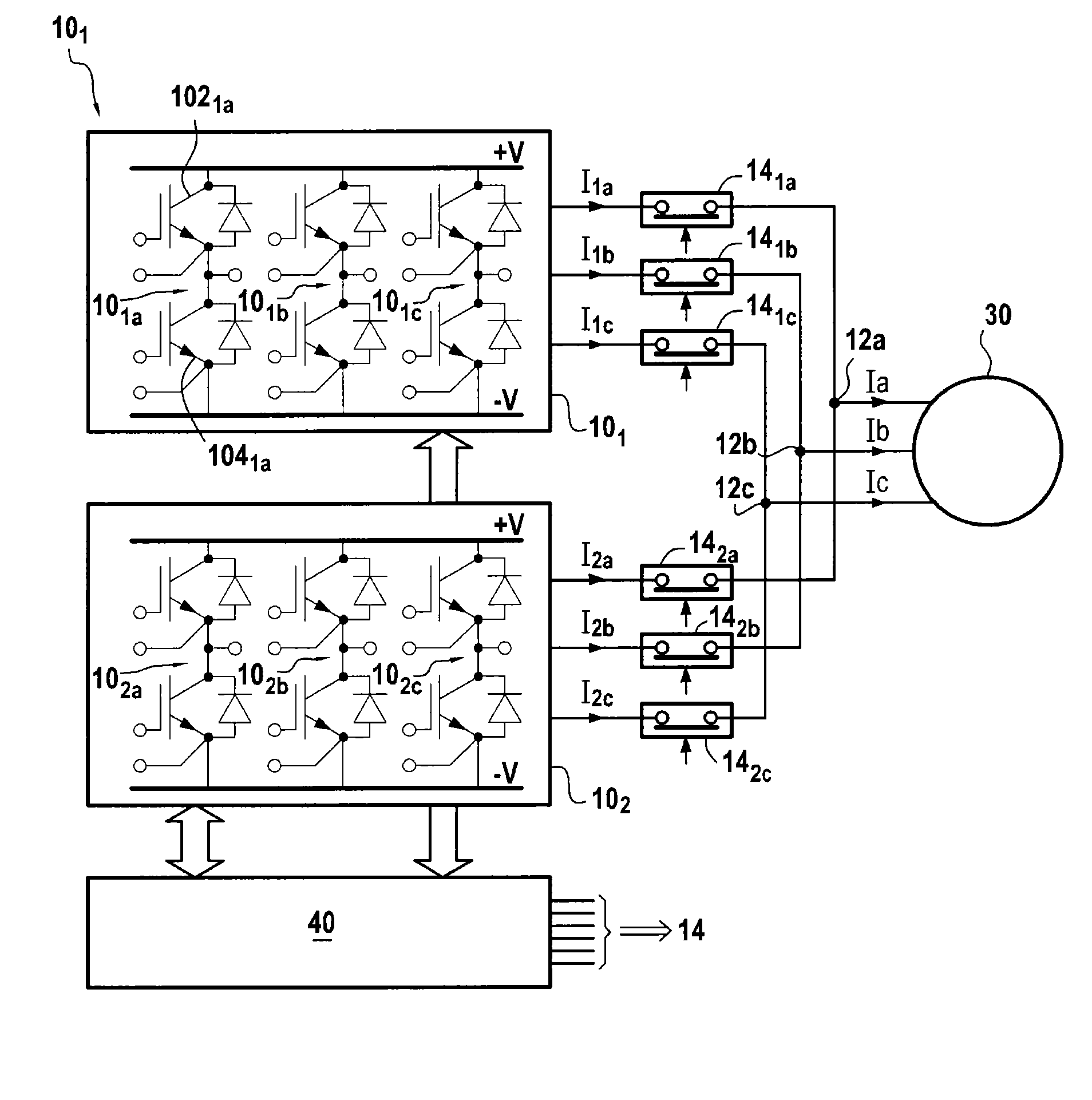
[0039]FIG. 3 is a diagram of an embodiment of a control device 10 of the invention for controlling a three-phase electrical machine 30 by means of two three-phase inverters 101 and 102 in parallel.

[0040]As mentioned above, the invention applies in particular to the field of aviation. The electrical machine 30 may be a machine in a system for starting an aeroengine, e.g. a turbine engine. The electrical machine is then mechanically coupled to a shaft of the engine in order to drive it on starting, the machine then being controlled in electric motor mode. The electrical machine 30 may also be a machine used for starting an auxiliary power unit (APU) or for activating actuators.

[0041]The inverter 101 has three branches 101a, 101b, and 101c that deliver alternating currents I1a, I1b, and I1c at respective output terminals 12a, 12b, and 12c of the control device. In similar manner, the inverter 102 has three branches 102a, 102b, and 102c that deliver alternating currents I2a, I2b, and I2...


PUM


Abstract

A polyphase electrical machine controlled by at least two parallel inverters, each including a number of branches equal to a number of phases of the machine and controlled by PWM. When detecting an inverter branch is faulty, the faulty branch is isolated and the phase in question is powered by each corresponding other inverter branch. The PWM is modified to make power switches of each other branch conductive in succession, without switching while absolute value of the current of the phase in question is greater than or equal to a threshold of 80% to 120% of (n−1)Imax / n, n is number of inverters and Imax is maximum magnitude of the phase current. It is thus possible to continue generating substantially sinusoidal voltages on each of the phases, while avoiding overdimensioning the power switches to ensure in event of a fault they can deliver currents of amplitude higher than in normal operation.

Description

BACKGROUND OF THE INVENTION[0001]The invention relates to controlling a polyphase electrical machine by means of a plurality of inverters in parallel.[0002]The invention applies more particularly to situations in which such control must present a high degree of reliability, e.g. in the field of aviation.[0003]A known device for controlling a three-phase electrical machine is shown in FIG. 1. The device has two three-phase inverters 1 delivering respective alternating currents (AC) Ia, Ib, and Ic to the phase windings of the electrical machine 4, each inverter supplying about half of each phase current. Each inverter has switches 5 in a bridge circuit, e.g. power transistors. Each inverter has three branches 6, each comprising two power switches 5 connected in series between two opposite terminals +V and −V of a direct current (DC) electrical power supply, and connected to opposite sides of a point 7 that is connected to a respective phase of the electrical machine. A three-pole isol...

Claims


Application Information

Patent Timeline
Patent Type & Authority Patents(United States)
IPC IPC(8): H02P6/14
CPCH02P29/022H02M7/493H02P29/032
Inventor DE, WERGIFOSSE, ERIC
Owner SAFRAN ELECTRICAL & POWER
Why Eureka
Try Eureka