Centrifugal chiller performance evaluation system

a centrifugal chiller and performance evaluation technology, applied in the field of centrifugal chiller performance evaluation system, can solve the problems of inability to iteratively calculate, and the design cop calculation is almost impossible in a refrigerator control panel with a limited throughpu

Active Publication Date: 2014-08-19
MITSUBISHI HEAVY IND LTD
View PDF22 Cites 6 Cited by
  • Summary
  • Abstract
  • Description
  • Claims
  • Application Information

AI Technical Summary

Benefits of technology

[0011]According to the above aspect, the characteristics of the ideal actual-machine COP in an ideal environment are expressed using the computational formula showing the COP characteristics of the reverse Carnot cycle, and the losses varying with the load factor and the cooling water inlet temperature are expressed by the first correction value determined by the load factor and the second correction value calculated from the second computational formula including the difference between cooling water outlet temperature and chilled water outlet temperature as a variable. In this way, the computational formula for the design COP, which is expressed by an extremely complicated computational formula in the related art, can be sufficiently expressed by a simple computational formula to perform iterative computation of the design COP. In addition, the above performance evaluation system provides the notable advantage of allowing even a device having a limited throughput, such as a centrifugal chiller control panel, to perform iterative computation of the design COP.
[0013]In this way, an error due to a design point of rated specification conditions can be eliminated so that the design COP computational formula has higher versatility.
[0015]Because heat loss occurring during heat exchange in the centrifugal chiller is compensated for, the design COP can be calculated with higher precision.
[0019]For example, if design COP is calculated by a device installed at another site remote from a centrifugal chiller, operating data acquired from the centrifugal chiller must be transmitted to that device in real time via, for example, a communication medium. On the other hand, the operating data is constantly input to the control panel of the centrifugal chiller to control the centrifugal chiller. If the control panel has the function of calculating the design COP, the design COP can be calculated using the operating data used for control. This eliminates the need for the burdensome data communication described above.
[0020]The present invention provides the advantage of allowing iterative computation of the design COP.

Problems solved by technology

Accordingly, it is impractical to iteratively calculate the constantly varying design COP, and it is almost impossible to handle such calculation of the design COP in a refrigerator control panel which has a limited throughput.

Method used


Image

  • Centrifugal chiller performance evaluation system
  • Centrifugal chiller performance evaluation system
  • Centrifugal chiller performance evaluation system

Examples


Embodiment Construction

[0029]A centrifugal chiller performance evaluation system according to an embodiment of the present invention will now be described with reference to the drawings.

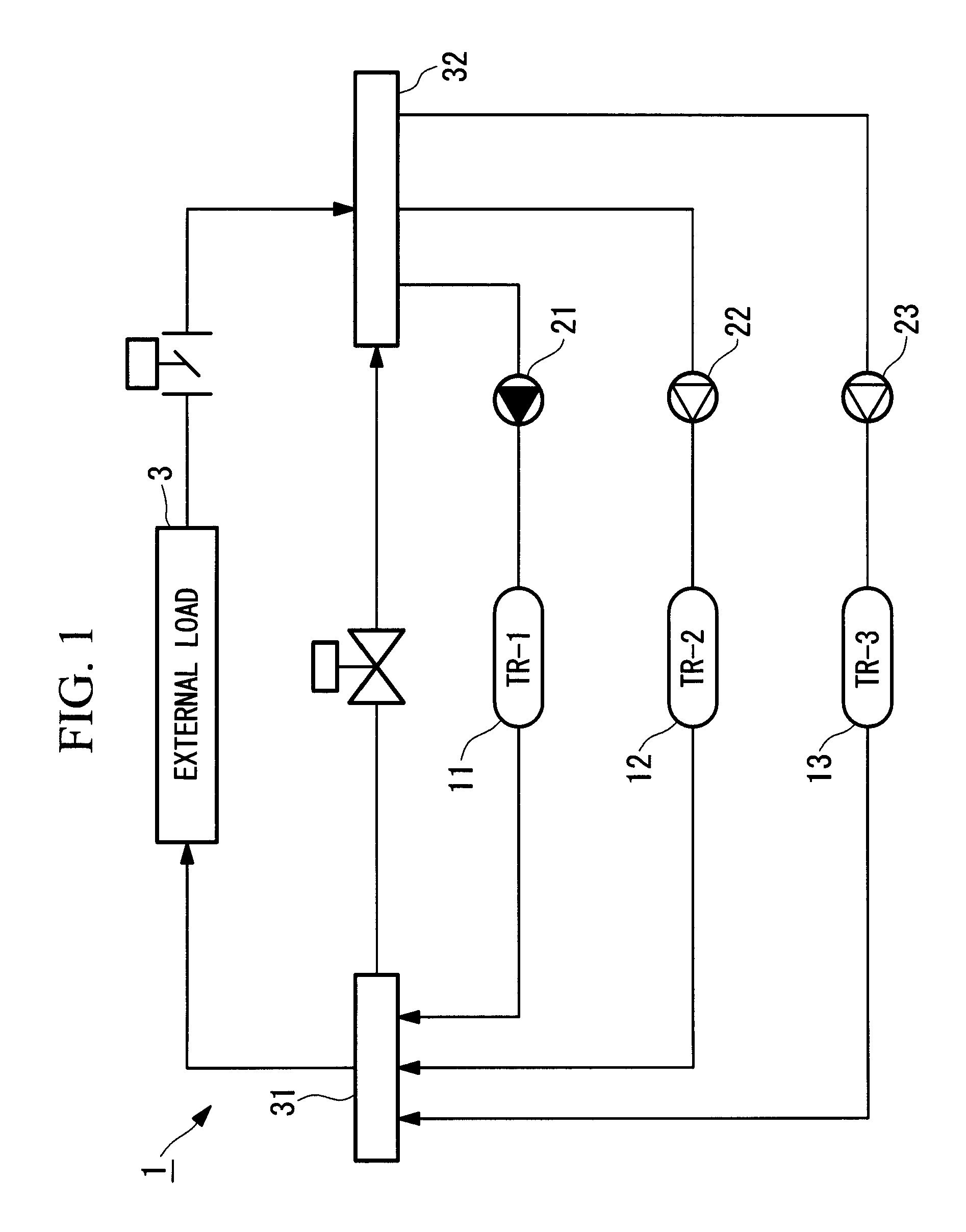
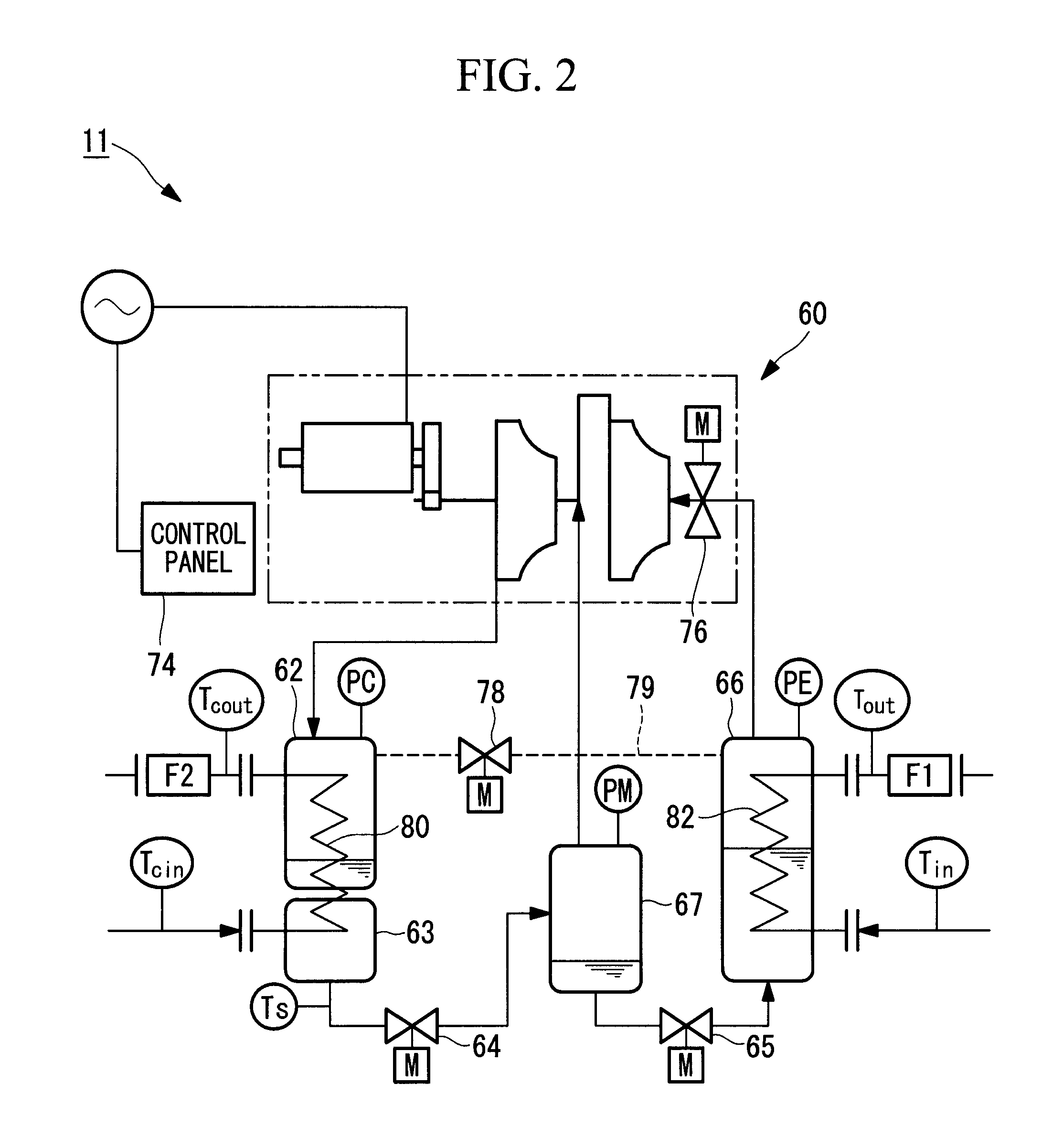
[0030]First, the arrangement of centrifugal chillers to which the centrifugal chiller performance evaluation system is applied will be briefly described using FIGS. 1 and 2. FIG. 1 is a diagram schematically showing the configuration of a heat source system including centrifugal chillers according to this embodiment. A heat source system 1 is installed in, for example, a building or plant facility and includes three centrifugal chillers 11, 12, and 13 for cooling chilled water (heat medium) supplied to an external load 3 such as an air conditioner or a fan coil. These centrifugal chillers 11, 12, and 13 are arranged in parallel with the external load 3.

[0031]Chilled water pumps 21, 22, and 23 for pumping the chilled water are disposed upstream of the centrifugal chillers 11, 12, and 13, respectively, as viewed along the fl...


PUM


Abstract

Design COP is iteratively computed. Provided is a centrifugal chiller performance evaluation system including a data acquisition section for acquiring operating data from a centrifugal chiller as input data; a storage section storing a design COP estimation formula obtained by adding correction values corresponding to losses occurring in an actual environment to a computational formula for ideal actual-machine COP expressed using COP characteristics of a reverse Carnot cycle; and a computing section for estimating a design COP at a current operating point using the operating data acquired by the data acquisition section and the design COP estimation formula stored in the storage section. The correction values include a first correction value calculated from a first computational formula including the load factor of the centrifugal chiller as a variable and a second correction value calculated from a second computational formula including a difference between cooling water outlet temperature and chilled water outlet temperature as a variable. The second correction value contains an offset from the first correction value depending on cooling water inlet temperature.

Description

BACKGROUND OF THE INVENTION[0001]1. Field of the Invention[0002]The present invention relates to performance evaluation systems for centrifugal chillers that include fixed-speed turbocompressors.[0003]This application is based on Japanese Patent Application No. 2010-170665, the content of which is incorporated herein by reference.[0004]2. Description of Related Art[0005]Recently, the need for performance evaluation of centrifugal chillers has been growing with the increasing social concern about reductions in energy consumption and CO2 emissions as countermeasures against global warming. In general, the performance of centrifugal chillers is evaluated using a measure called the coefficient of performance (COP) (see, for example, Japanese Unexamined Patent Application, Publication No. HEI-11-23113). The COP is calculated from the following formula, where a higher COP is evaluated as having a higher energy efficiency.COP=cooling capacity[kW] / power consumption[kW][0006]One possible met...

Claims


Application Information

Patent Timeline
Patent Type & Authority Patents(United States)
IPC IPC(8): G06F17/10
CPCF25B1/053F25B49/02F25B2500/18F25B2500/19F25D17/02F25B2339/047F25B2700/21161F25B2700/21173G01M99/00
Inventor TOGANO, YOSHIEUEDA, KENJIMATSUO, MINORU
Owner MITSUBISHI HEAVY IND LTD
Why Eureka
Try Eureka