Multi-mode heater for a diesel emission fluid tank

a technology of diesel emission and fluid tank, which is applied in the field of heater assembly, can solve the problems of diesel emissions and the freezing temperature of aqueous urea solution about 11° c, and achieve the effect of improving heat flow and reducing heat loss

Active Publication Date: 2014-09-02
SHAW DEV
View PDF161 Cites 6 Cited by
  • Summary
  • Abstract
  • Description
  • Claims
  • Application Information

AI Technical Summary

Benefits of technology

[0010]According to another concept of the present invention, thermal insulation may be used to reduce heat loss and improve heat flow to the fluid in the tank.

Problems solved by technology

Diesel emissions are an environmental concern that has limited application of diesel engines despite the fuel efficiency offered by these engines.
One drawback, however, is the freezing temperature for Aqueous Urea Solution is about −11° C.

Method used


Image

  • Multi-mode heater for a diesel emission fluid tank
  • Multi-mode heater for a diesel emission fluid tank
  • Multi-mode heater for a diesel emission fluid tank

Examples


Embodiment Construction

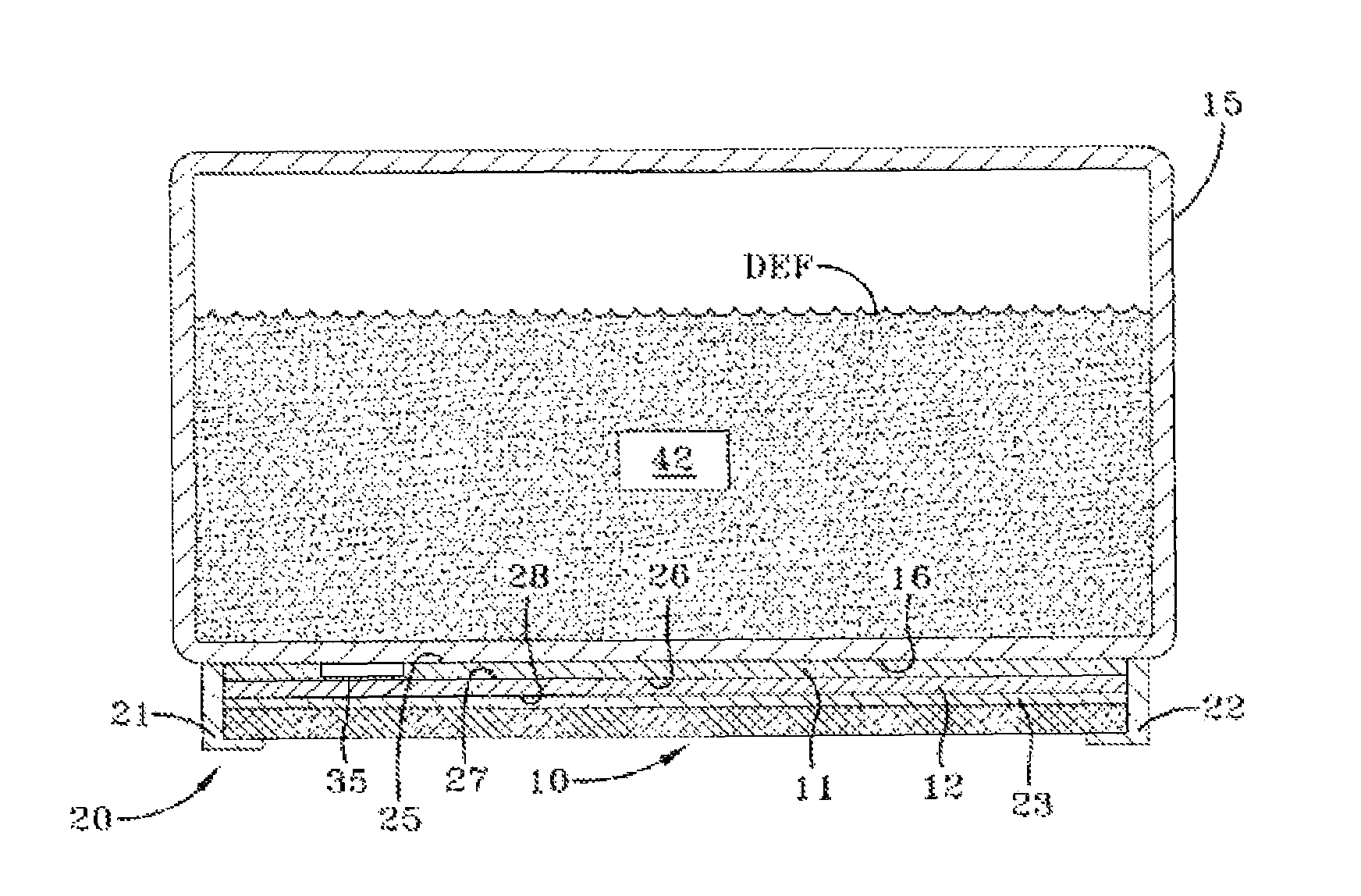
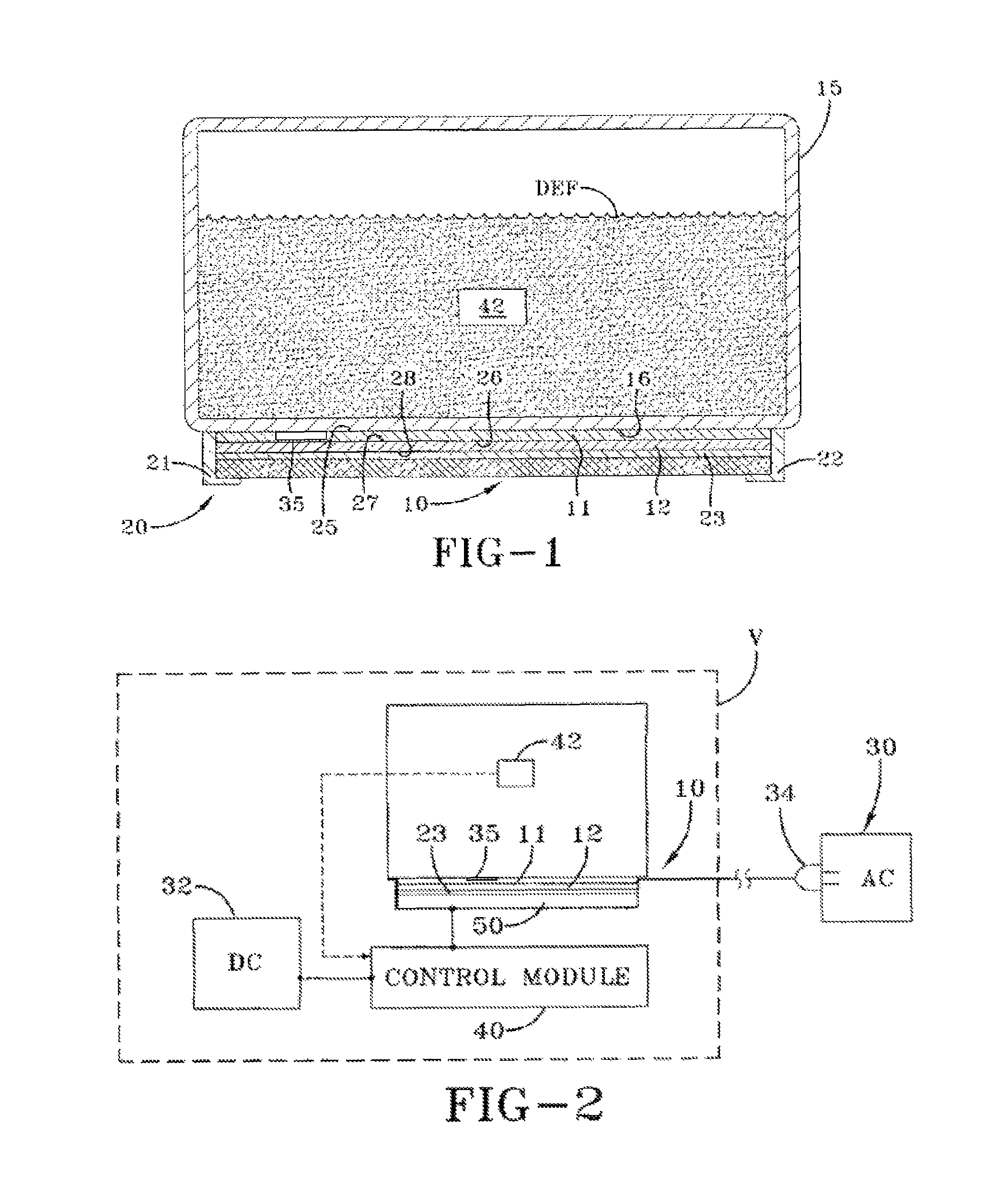
[0016]A multimode heater assembly according to the concepts of the present invention is generally indicated by the number 10 in the accompanying drawings. Heater assembly 10 is used in connection with a tank 15 for holding a diesel emissions fluid (DEF). Tank 15 is generally a container capable of holding DEF for use in a vehicle V. Tank 15 has an outer surface that includes a base 16. The DEF may be an aqueous urea solution (AUS). To prevent the AUS from freezing, heater assembly 10 may be used in connection with tank 15 to maintain the DEF above its freezing temperature, for example, −11° C. for AUS. A heater assembly 10 generally includes a first heating element or first heater 11 and a second heating element or second heater 12. The first heater 11 is a higher power heater relative to the second heater 12. To that end, first heater 11 provides more intense heat to the DEF tank 15 than second heater 12. For example, in a locomotive application, first heater may be a 1,500 watt he...


PUM


Abstract

A heater assembly used in connection with a diesel emissions fluid tank in a vehicle, the heater assembly including a first heater connectable to an alternating current power supply; a second heater connectable to a direct current power supply within the vehicle; wherein the first heater is adapted to operate at a higher power than the second heater; wherein the first heater is closer to the tank than the second heater; a temperature sensor in sensing communication with the tank and adapted to provide a tank temperature; a control circuit connected to the second heater and the vehicle power supply, wherein the temperature sensor communicates the tank temperature to the control circuit, wherein the control circuit selectively activates the second heater to obtain a desired tank temperature.

Description

TECHNICAL FIELD[0001]In general, the present invention relates to a heater assembly used in connection with diesel exhaust fluid in a tank. In particular, the present invention relates to a multiple mode heater assembly having a high power heater adjacent to the tank and a lower power heater located outward of the high power heater to separately apply higher and lower power heat to the tank to prevent freezing.BACKGROUND OF THE INVENTION[0002]Diesel emissions are an environmental concern that has limited application of diesel engines despite the fuel efficiency offered by these engines. To reduce harmful emissions, technologies that treat the exhaust gas downstream of the engine have been developed including selective catalytic reduction systems that inject a small quantity of diesel exhaust fluid (DEF) into the exhaust upstream of a catalyst where is vaporizes and decomposes to form ammonia and carbon dioxide. The ammonia (NH3) converts nitrogen oxides (NOx) within the exhaust gas ...

Claims


Application Information

Patent Timeline
Patent Type & Authority Patents(United States)
IPC IPC(8): H05B3/02F02M31/125
CPCF02M31/125Y02T10/126Y10T137/6416Y10T137/6606Y02T10/12
Inventor KOONCE, JOHN, ROSS
Owner SHAW DEV
Why Eureka
Try Eureka