Apparatuses, circuits, and methods for reducing metastability in data synchronization

a data synchronization and metastability technology, applied in the field of integrated circuits, can solve problems such as insufficient charge or discharge of inability to fully charge or discharge one or more nodes, and output that is invalid logic level for an unacceptable period of tim

Active Publication Date: 2014-09-02
MICRON TECH INC
View PDF5 Cites 7 Cited by
  • Summary
  • Abstract
  • Description
  • Claims
  • Application Information

AI Technical Summary

Problems solved by technology

The invalid logic level may result from the one or more nodes not being fully charged or discharged when the flip-flop latches the input signal at the rising clock edge because, for example, the one or more nodes did not get fully pulled-up or fully pulled-down.
The output may, for example, linger at an invalid logic level for an unacceptable period of time.
Alternatively, or in addition to the output lingering at an invalid logic level, the output may not correctly correspond to the input signal because the output may transition too early or too late (i.e., have an incorrect phase).
In some cases, the phase of the output will be correct, but the width of the output pulse will be incorrect.
The lingering, the incorrect phase, and / or the incorrect pulse width resulting from the metastability may cause unintended operation of a circuit or apparatus that receives the output of the flip-flop.
Although such serial chaining of flip-flops may reduce the likelihood that the output signal of the serial chain lingers, this approach generally does not address the root cause of the metastability (e.g., latch nodes that do not get fully charged or discharged before the flip-flop latches) and instead simply mitigates some of the consequences from when a flip-flop experiences metastability.
Furthermore, serial chaining of flip-flops tends to consume power, present additional clock and signal loading, and add delay to a signal path, all of which may be undesirable in some cases.

Method used


Image

  • Apparatuses, circuits, and methods for reducing metastability in data synchronization
  • Apparatuses, circuits, and methods for reducing metastability in data synchronization
  • Apparatuses, circuits, and methods for reducing metastability in data synchronization

Examples


Embodiment Construction

[0017]Certain details are set forth below to provide a sufficient understanding of embodiments of the invention. However, it will be clear to one skilled in the art that embodiments of the invention may be practiced without these particular details. Moreover, the particular embodiments of the present invention described herein are provided by way of example and should not be used to limit the scope of the invention to these particular embodiments. In other instances, well-known circuits, control signals, timing protocols, and software operations have not been shown in detail in order to avoid unnecessarily obscuring the invention.

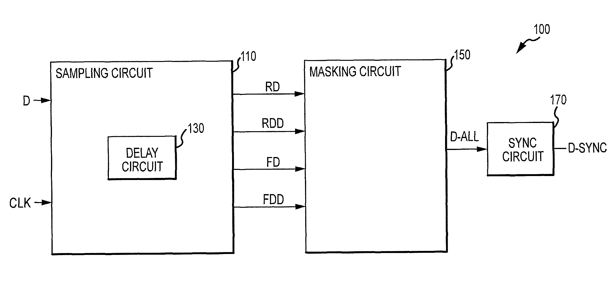
[0018]FIG. 1 illustrates an apparatus 100 according to an embodiment of the invention. The apparatus 100 receives a data input signal D and a latching signal CLK. The data input signal D may be asynchronous in some embodiments. The latching signal CLK may be a clock signal in some embodiments, although in other embodiments, a gating signal or any other type...


PUM


Abstract

Apparatuses, circuits, and methods are disclosed for reducing or eliminating unintended operation resulting from metastability in data synchronization. In one such example apparatus, a sampling circuit is configured to provide four samples of a data input signal. A first and a second of the four samples are associated with a first edge of a latching signal, and a third and a fourth of the four samples are associated with a second edge of the latching signal. A masking circuit is configured to selectively mask a signal corresponding to one of the four samples responsive to the four samples not sharing a common logic level. The masking circuit is also configured to provide a decision signal responsive to selectively masking or not masking the signal.

Description

TECHNICAL FIELD[0001]Embodiments of the invention relate generally to integrated circuits, and more particularly, in one or more of the illustrated embodiments, to reducing or eliminating metastability in data synchronization.BACKGROUND OF THE INVENTION[0002]Metastability is a reliability concern where a plurality of different signals are provided to a circuit at the same or at nearly the same time, including where an asynchronous signal is to be synchronized with a latching signal (e.g., a clock signal). In a rising edge triggered flip-flop, for example, if an input signal transitions right before a rising clock edge and violates the setup time of the flip-flop, if the input signal transitions at the same time as the rising clock edge, or if the input signal transitions right after the rising clock edge and violates the hold time of the flip-flop, then the flip-flop may at least temporarily enter a metastable state. The metastable state may be that one or more nodes of the flip-flo...

Claims


Application Information

Patent Timeline
Patent Type & Authority Patents(United States)
IPC IPC(8): H04L7/00
CPCH03L7/0816H03L7/0818H03K19/00346G11C7/222G11C7/1009H03L7/0814H03K3/0375
Inventor MA, YANTAO
Owner MICRON TECH INC
Why Eureka
Try Eureka