
Humidity control apparatus

a technology of humidity control and control apparatus, which is applied in the direction of ventilation systems, heating types, instruments, etc., can solve the problems of reducing maintenance efficiency, difficult maintenance of dampers, and the possibility of damper plurality, so as to reduce space and improve efficiency. , the effect of reducing the space required

Active Publication Date: 2014-09-09
DAIKIN IND LTD
View PDF16 Cites 2 Cited by
  • Summary
  • Abstract
  • Description
  • Claims
  • Application Information

AI Technical Summary

Benefits of technology

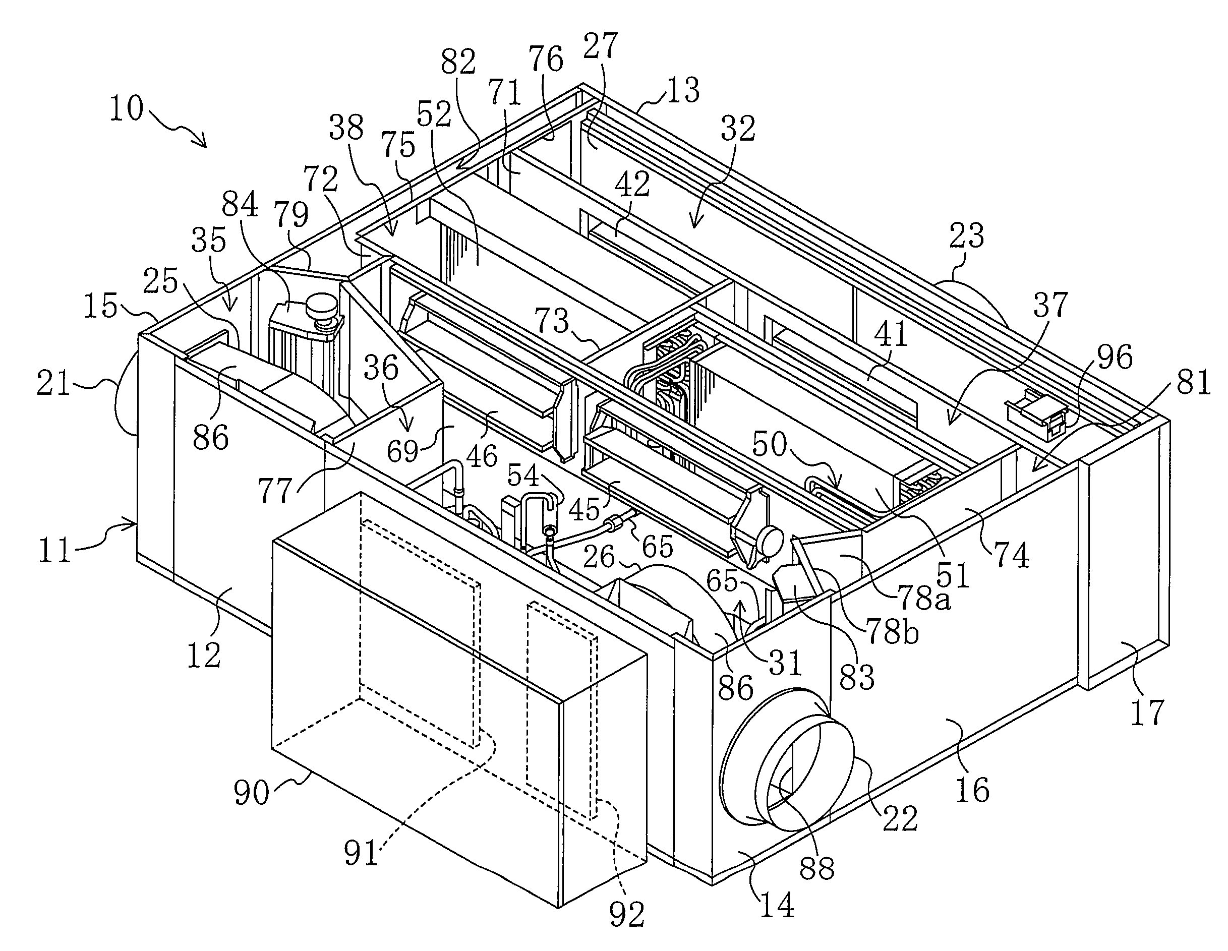
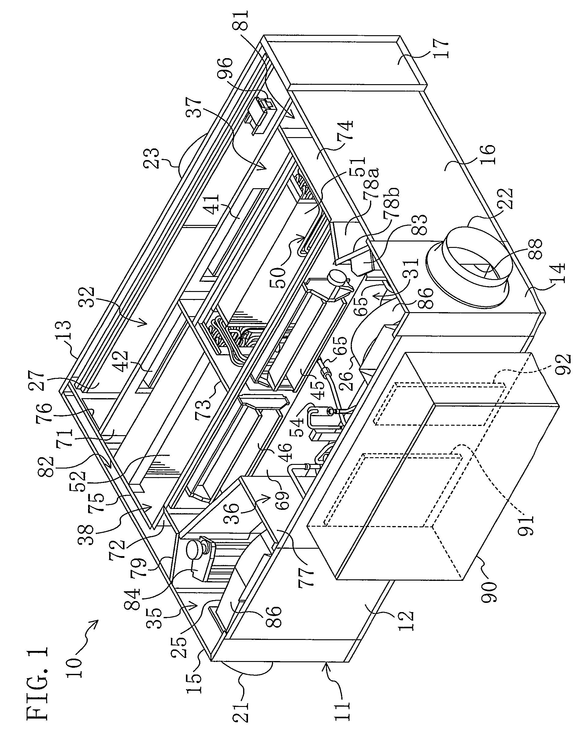
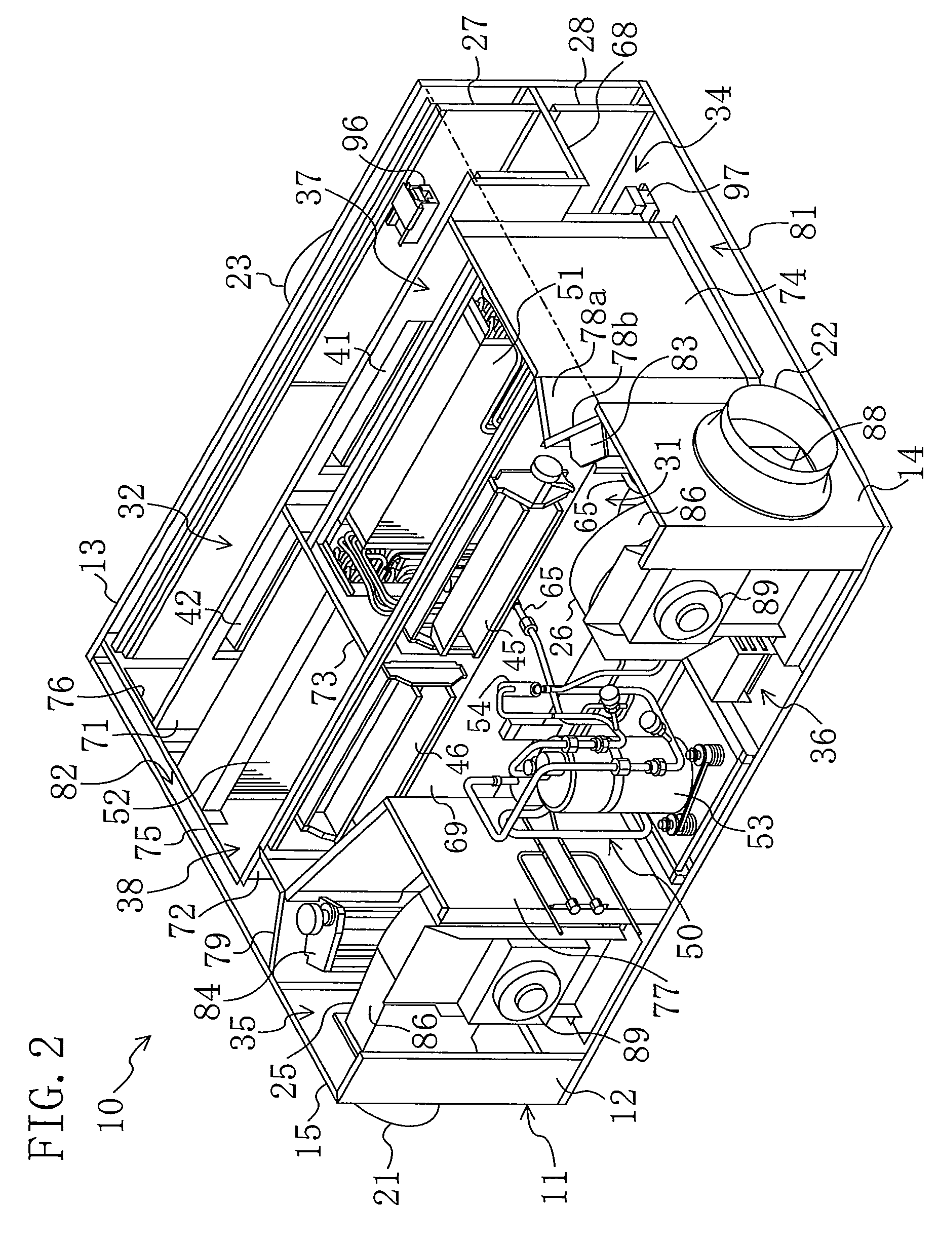
[0032]According to the present invention, the coupling member (152, 162) for separably coupling the adjacent dampers (41-48) together is provided. Thus, the invention makes it possible to draw out or attach the plurality of dampers (41-48) coupled by the coupling member (152, 162) together. Therefore, for example, in comparison with the case where the dampers are detached / attached one by one, maintenance of the dampers (41-48) can be performed with improved efficiency. In the present invention, the dampers (41-48) are separated while drawing the damper unit (100) out, thereby reducing space required to draw the dampers (41-48) out. Further, the damper unit (100) can be placed in the casing while coupling the dampers (41-48), thereby reducing space required for the attachment of the dampers (41-48). Therefore, limitation on the installation location of the humidity control apparatus is alleviated due to the reduction of the space for the maintenance of the plurality of dampers (41-48).
[0033]According to the second aspect of the invention, the rail (141-144) for guiding the dampers (41-48) is provided. This makes the detachment / attachment of the dampers (41-48) easier, thereby improving efficiency of the maintenance.
[0034]According to the third aspect of the invention, the engagement sections (152, 162) are arranged on the coupling ends of the adjacent dampers (41-48), and the engagement sections (152, 162) are prevented from disengaging in the drawing direction. Therefore, according to the invention, disengagement of the dampers (41-48) at the start of the drawing of the damper unit (100) can be avoided, thereby allowing for reliably drawing the dampers (41-48) out together.
[0035]According to the fourth aspect of the invention, the flat protrusion (152) is arranged on the coupling end of one of the adjacent dampers (41-48), and the flat hook (162) is arranged on the coupling end of the other damper. Thus, the invention makes it possible to reliably draw the dampers (41-48) out together by hooking the flat hook (162) on the flat protrusion (152) in drawing the damper unit (100) out. The flat protrusion (152) can easily be detached from the flat hook (162) by moving the flat hook (162) orthogonally to the drawing direction relative to the flat protrusion (152). This allows for easy separation of the dampers (41-48), thereby improving the maintenance efficiency to a further extent.
[0036]According to the sixth aspect of the invention, the damper unit (100) is drawn out in the direction of alignment of the dampers (41-48). With the dampers (41-48) configured to be separable, the length of the space required to draw out or attach the dampers (41-48) can effectively be reduced.
[0037]In particular, according to the seventh aspect of the invention, the plurality of damper units (100) can be drawn out in the same direction. Therefore, the space for the maintenance of the dampers (41-48) can be concentrated on the same side of the casing (11). This allows for further reduction of the space for maintenance of the dampers (41-48).
[0038]According to the fifth and eighth aspects of the invention, leakage of the air through the gap formed between the coupling ends of the dampers (41-48) of the damper unit (100) can reliably be prevented. This can prevent change in humidity of the air due to the air leakage after the humidity control has been done.

Problems solved by technology

However, the provision of the plurality of dampers involves difficult maintenance of the dampers.
Specifically, when the dampers are independently arranged, attachment and detachment of the dampers are complicated, thereby reducing efficiency of the maintenance.

Method used


Image

  • Humidity control apparatus
  • Humidity control apparatus
  • Humidity control apparatus

Examples


embodiment

Advantages of Embodiment

[0160]In the above-described embodiment, a coupling member (152, 162) for separably coupling the adjacent dampers (41-48) is provided in the damper unit (100). This makes it possible to draw out or attach the adjacent dampers (41-48) coupled by the coupling member (152, 162) together. Therefore, for example, in comparison with the case where the dampers are detached / attached one by one, maintenance of the dampers (41-48) can be performed with improved efficiency. In the above-described embodiment, the front damper (41, 43, 45, 47) is separated while drawing the damper unit (100) out, thereby reducing space required to detach / attach the dampers (41-48). Thus, limitation on the installation location of the humidity control apparatus (10) is alleviated. Therefore, for example, in the case where the humidity control apparatus (10) is installed on the ceiling, sufficient space for maintenance of the dampers (41-48) can be ensured.

[0161]In the above-described embod...


PUM


Abstract

A plurality of humidity control chambers are provided in a casing. An open / close damper is provided for each of a plurality of air flow ports communicating with the humidity control chambers. Adjacent dampers of the plurality of dampers are separably coupled together by a coupling member.

Description

TECHNICAL FIELD[0001]The present invention relates to humidity control apparatuses for controlling humidity of air, particularly to humidity control apparatuses including a plurality of dampers for opening / closing air flow ports communicating with a plurality of humidity control chambers for controlling the air humidity.BACKGROUND ART[0002]Humidity control apparatus for controlling humidities of outdoor air and indoor air, and supplying the humidity-controlled air to the inside of a room have been known. Patent Document 1 shows a humidity control apparatus including an adsorption heat exchanger carrying an adsorbent on a surface thereof.[0003]The humidity control apparatus of Patent Document 1 includes a first adsorption heat exchanger placed in a first humidity control chamber, and a second adsorption heat exchanger placed in a second humidity control chamber. The adsorption heat exchangers are connected to a refrigerant circuit. The refrigerant circuit alternately performs operati...

Claims


Application Information

Patent Timeline
Patent Type & Authority Patents(United States)
IPC IPC(8): F24F3/14F24F7/00B25G3/18F24F11/00
CPCF24F11/0008F24F3/1429F24F3/1405F24F3/1411F24F11/0015Y10T403/592F24F2221/36F24F13/14F24F11/30F24F2110/20
Inventor NARIKAWA, YOSHINORI
Owner DAIKIN IND LTD
Learn More