

Integrated TBC and cooling flow metering plate in turbine vane
- Summary
- Abstract
- Description
- Claims
- Application Information
AI Technical Summary
Benefits of technology
Problems solved by technology
Method used
Image

Examples
first embodiment
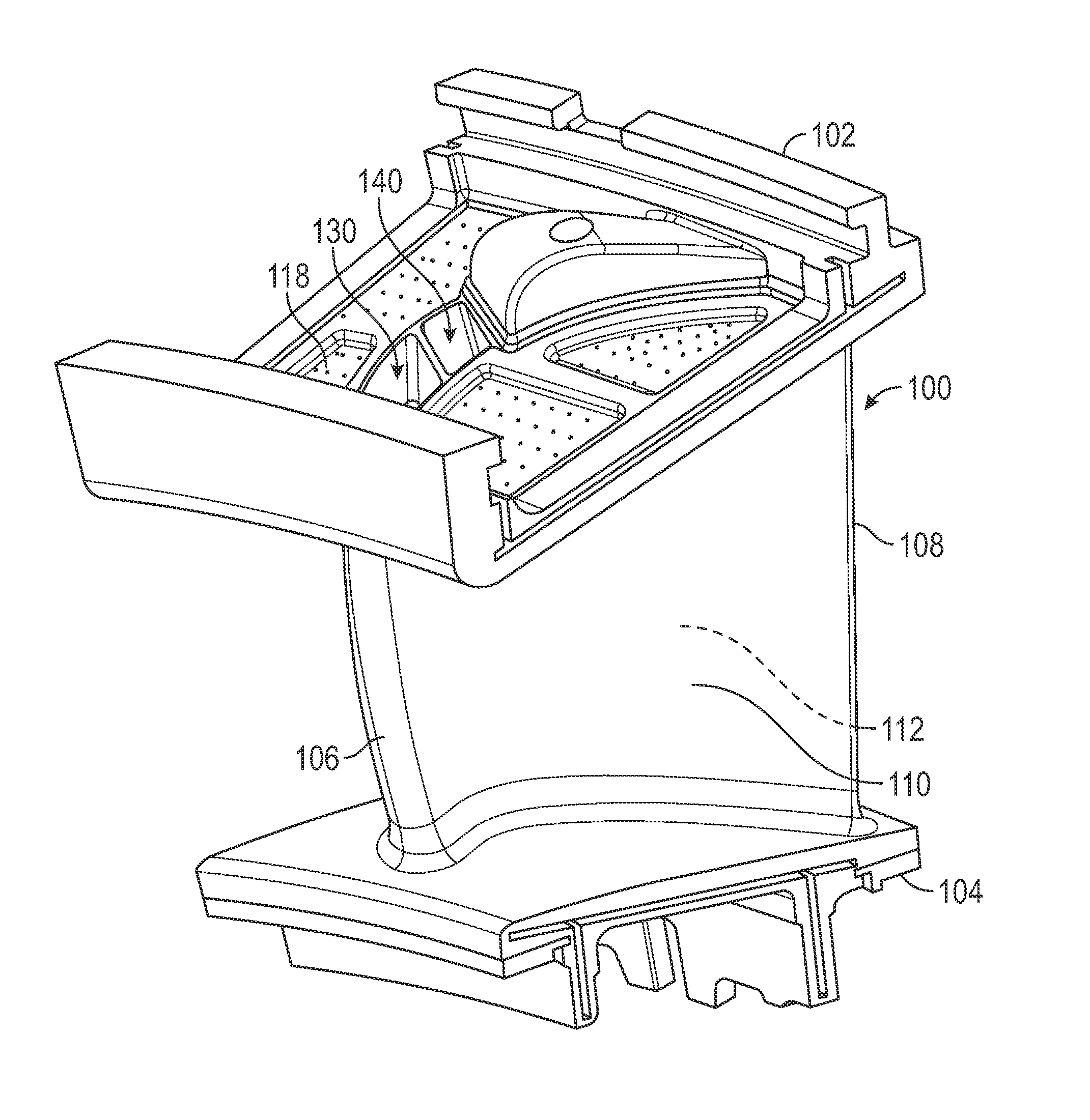
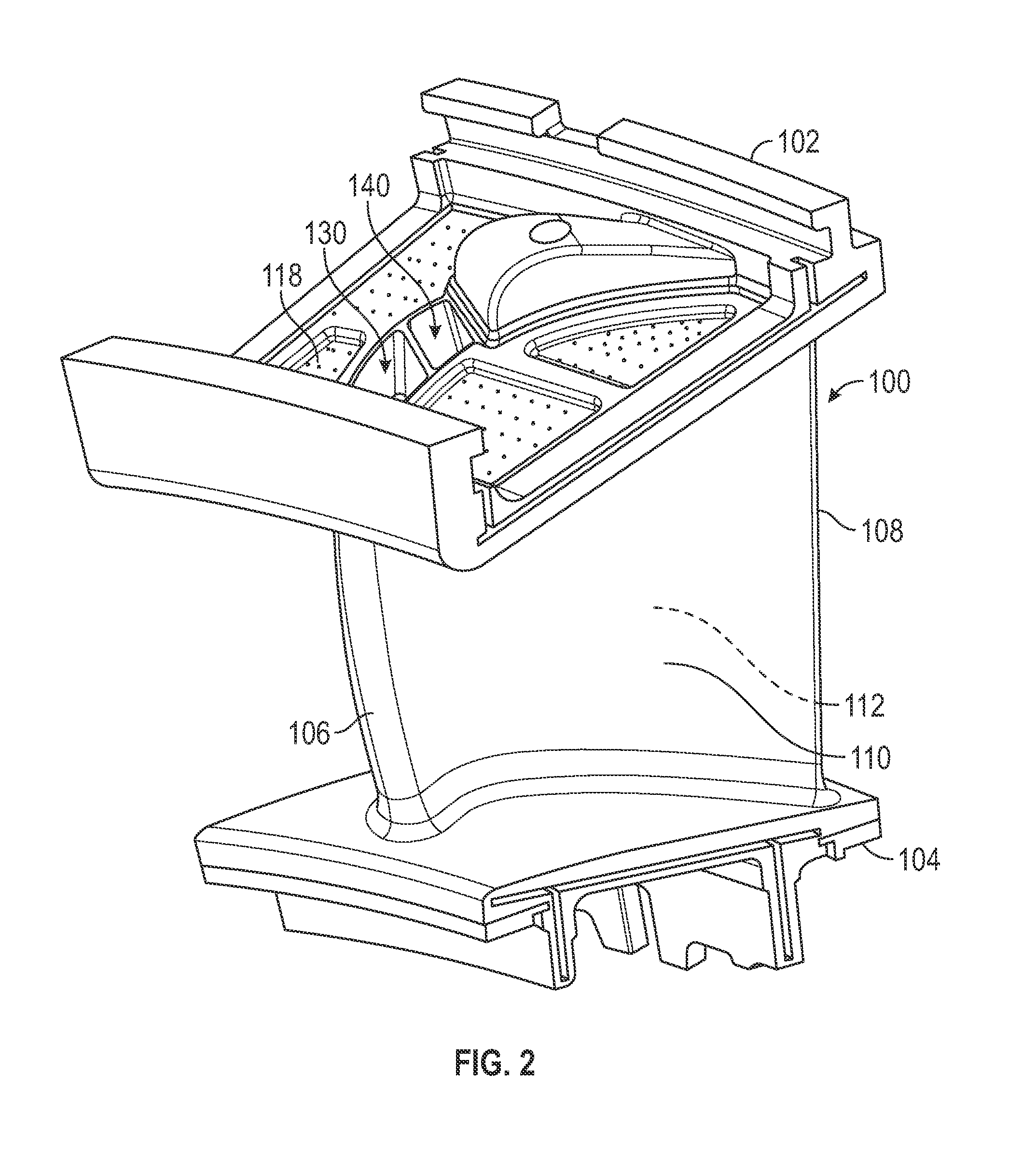
[0043]FIG. 9 is an illustration of a flow control insert device which can be placed into the trailing edge cooling passage inlet 140. Flow control insert 200 is, in one preferred embodiment, a thin strip of metal formed with a wavy shape. As shown in FIG. 9, the flow control insert 200 is shaped to fit down into the trailing edge cooling passage inlet 140, inside the trailing edge cooling passage 142, where it causes the cooling air flow to be directed against the walls 144 of the vane 100. Specifically, the insert 200 causes the cooling air flow to be directed against the walls on the pressure side 110 and the suction side 112 of the vane 100—not the interior-facing walls which separate the leading edge cooling passage 132 and the trailing edge cooling passage 142. The air flow acceleration and lateral velocity caused by the flow control insert 200 increases the convective heat transfer between the walls 144 and the cooling air, thus allowing a cooling air flow rate reduction while...
second embodiment
[0045]FIG. 10 is an illustration of a flow control insert device which can be placed into the trailing edge cooling passage inlet 140. Flow control insert 210 is, in one preferred embodiment, a thin strip of metal formed into a twisted shape. As shown in FIG. 10, the flow control insert210 is shaped to fit down into the trailing edge cooling passage inlet 140, inside the trailing edge cooling passage 142, where it causes the cooling air flow to swirl against the walls 144 of the vane 100. The flow control insert 210 offers the advantage of creating a swirling or twisting flow pattern in the cooling air which continues throughout the serpentine length of the trailing edge cooling passage 142. The swirling air flow motion caused by the flow control insert 210 increases the convective heat transfer between the walls 144 and the cooling air, thus allowing a cooling air flow rate reduction while maintaining vane temperature within specification. The insert 210 also serves as an obstructi...
PUM
 Abstract
Description
Claims
Application Information