Magnetic head, method for producing the magnetic head, and magnetic recording/reproducing apparatus

a technology of magnetic head and head, which is applied in the direction of recording information storage, instruments, transportation and packaging, etc., can solve the problems of difficult to form a fine width realizing the density exceeding 1 tb/in, the width of the high-frequency magnetic field of the oscillator in the track width direction cannot be decreased, and it is difficult to achieve fine widths exceeding 1 tb/in. achieve high-density recording, reduce the width of the high-frequency magnetic field from the oscil

Inactive Publication Date: 2014-09-09
HITACHI LTD
View PDF7 Cites 5 Cited by
  • Summary
  • Abstract
  • Description
  • Claims
  • Application Information

AI Technical Summary

Benefits of technology

[0010]According to the aspect of the present invention, the width of the high-frequency magnetic field from the oscillator in the track width direction can be decreased to an extent that is difficult to be realized only by the conventional photolithography. The present invention also provides the semi-circular oscillator that can stably generate high frequency. According to these effects, a magnetic head that can realize high-density recording can be provided.

Problems solved by technology

However, it is presumed that the width of the oscillator with the density exceeding 1 Tb / in2 cannot be decreased only by a photolithography technique used in a conventional production of a magnetic head.
Specifically, the shape of the oscillator can greatly affect the oscillation state, but it is difficult to form a fine width realizing the density exceeding 1 Tb / in2 and to control the shape only by the patterning according to the photolithography technique used in the conventional production of a magnetic head.

Method used


Image

  • Magnetic head, method for producing the magnetic head, and magnetic recording/reproducing apparatus
  • Magnetic head, method for producing the magnetic head, and magnetic recording/reproducing apparatus
  • Magnetic head, method for producing the magnetic head, and magnetic recording/reproducing apparatus

Examples


first embodiment

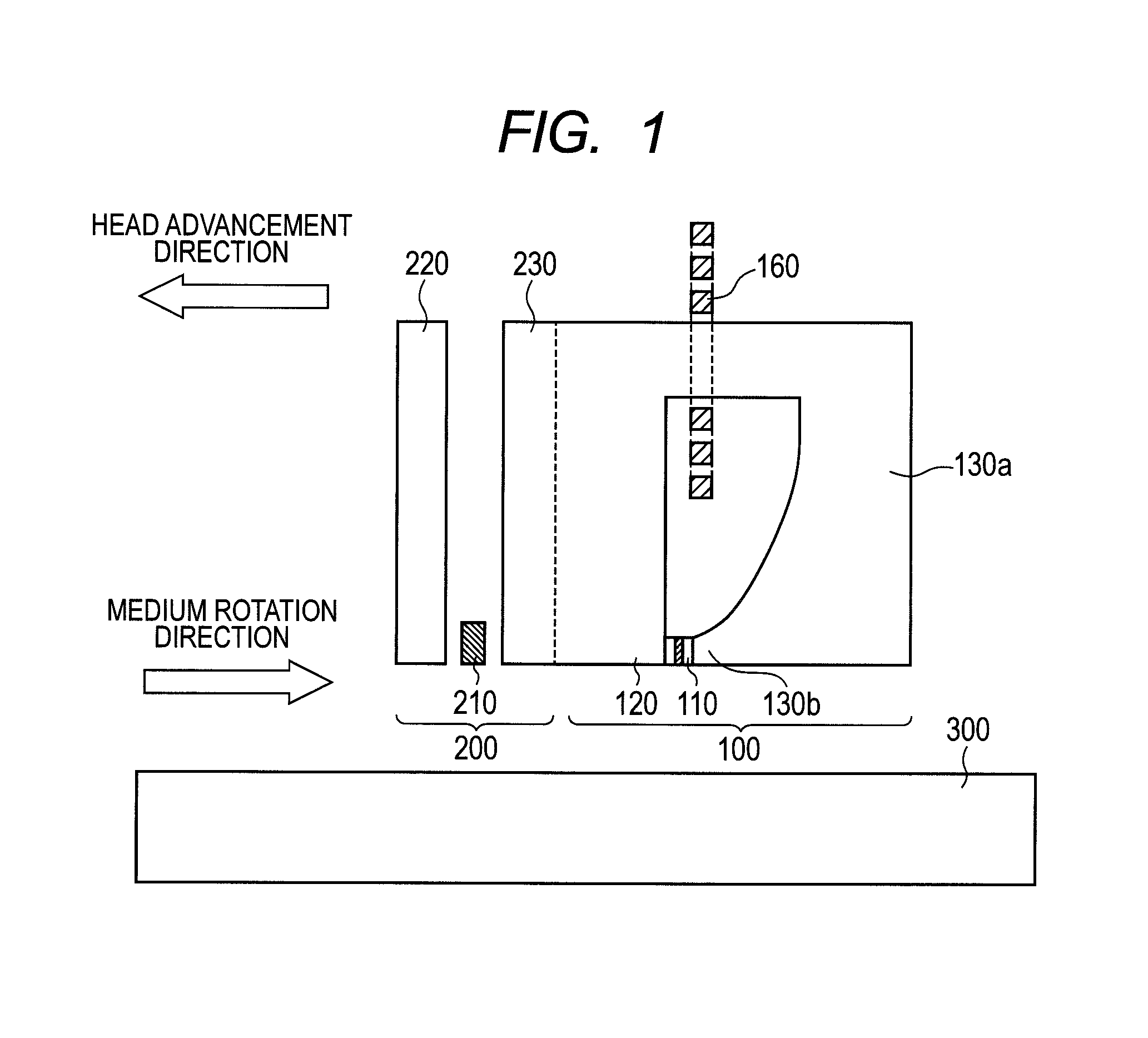
[0046]FIG. 1 is a schematic sectional view of a magnetic recording / reproducing head, according to one embodiment of the present invention, along a track direction. The magnetic recording / reproducing head (hereinafter merely referred to as magnetic head) is a magnetic head with separate recording and reproducing sections, and includes a recording section 100 and a reproducing section 200. The magnetic head records information and reproduces information to a rotating magnetic recording medium 300 such as a magnetic disk. The recording section 100 includes an oscillator 110 that generates a high-frequency magnetic field, a main pole 120 for generating a recording magnetic field, a coil 160 that excites a magnetizing field to the main pole 120, and a sub-pole 130a. In the example in FIG. 1, a trailing shield 130b is provided in the trailing direction of the main pole 120, but the trailing shield 130b is not necessarily provided. In this embodiment, the direction reverse to the advancing...

second embodiment

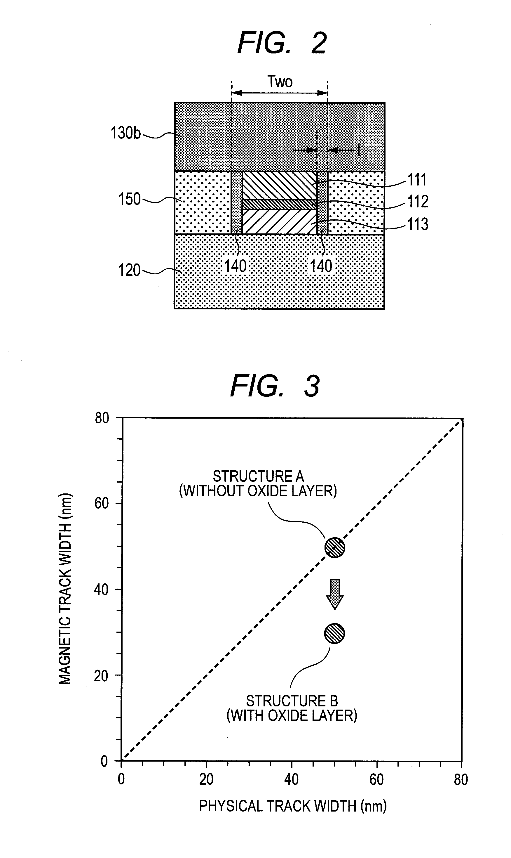
[0058]The second embodiment shows not only the effect obtained by the decrease in the magnetic track width in the first embodiment but also an effect of increasing the oscillation frequency of the high-frequency magnetic field from the oscillator by the formation of the oxide layer, the nitride layer, or the oxynitride layer.

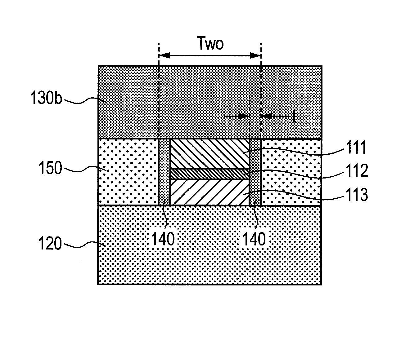
[0059]FIG. 4 is a schematic view of the oscillator in the recording head provided with the oxide layer 140 viewed from the trailing direction with the air bearing surface facing downward. The oxide layer 140 may be the nitride layer or the oxynitride layer. The feature of this embodiment is that the oscillator 110 covered by the oxide layer 140 has a semi-circular shape projecting in an element height direction. In other words, the oxide layer 140 is curved in the direction in which the oxide layer 140 spreads to the inside of the oscillator 110 from the air bearing surface to the far side in the element height direction. Like the first embodiment, the oxide lay...

third embodiment

[0062]The method for producing the oscillator 110 in the recording section will be described with reference to process drawings in FIGS. 7A to 7E. The present embodiment describes the case where the shape of the oscillator 110 becomes semi-circular due to the formation of the oxide layer 140 described in the second embodiment. In FIGS. 7A to 7E, the upper one is a schematic view of a cross-section perpendicular to a top surface of a substrate, as the oscillator 110 is viewed from the air bearing surface during the production process of the magnetic head, while the lower one is a schematic view, as the oscillator 110 is viewed from the trailing direction with the air bearing surface facing downward. ABS in these figures indicates a final position of the air bearing surface of the head. The portion near the substrate from the main pole 120 is not illustrated in FIGS. 7A to 7E.

[0063]Firstly, the pinned layer 113, the intermediate layer 112, and the FGL 111 forming the oscillator 110 ar...


PUM

PropertyMeasurementUnit
widthaaaaaaaaaa
widthaaaaaaaaaa
widthaaaaaaaaaa

Abstract

In a magnetic head of a high-frequency magnetic field assisted recording system, a width of a high-frequency magnetic field from an oscillator is decreased to enhance an oscillation frequency, in order to realize a high-density recording. An oscillator provided near a main pole, which generates a recording magnetic field, for generating a high-frequency magnetic field is patterned by a conventional photolithography, and then, an oxidation, nitridation, or oxynitridation is performed on the side face in a track width direction. With this process, an oxide layer, a nitride layer, or an oxynitride layer, which is made of a material of the oscillator, is formed on the side face of the oscillator in the track width direction, and the shape of the oscillator is formed to be semi-circular.

Description

CLAIM OF PRIORITY[0001]The present application claims priority from Japanese patent application JP 2012-037976 filed on Feb. 23, 2012, the content of which is hereby incorporated by reference into this application.FIELD OF THE INVENTION[0002]The present invention relates to a magnetic head, a method for producing the magnetic head, and a magnetic recording / reproducing apparatus, and more particularly to a magnetic head having a function of inducing magnetization reversal through an application of a high-frequency magnetic field to a magnetic recording medium, a method for producing the magnetic head, and a magnetic recording / reproducing apparatus including the magnetic head.BACKGROUND OF THE INVENTION[0003]In a magnetic recording / reproducing apparatus such as HDD (Hard Disk Drive), it is important to enhance recording capability in order to increase an areal recording density. Therefore, recent attention has been directed to assisted recording that temporarily reduces coercive force...

Claims


Application Information

Patent Timeline
Patent Type & Authority Patents(United States)
IPC IPC(8): G11B5/02
CPCG11B5/1276G11B5/1278G11B5/3146G11B5/3163G11B2005/0024Y10T428/115
Inventor SUGIURA, KENJIWATANABE, KATSUROIGARASHI, MASUKAZUSATO, YO
Owner HITACHI LTD
Why Eureka
Try Eureka