
Automatic detection device, system and method for inter-integrated circuit and serial general purpose input/output

a detection device and serial technology, applied in the direction of electric digital data processing, instruments, etc., can solve the problems of low setup cost and the need for resetting of the jumper, and achieve the effect of accelerating the relevant test of the target data transfer

Inactive Publication Date: 2014-09-09
INVENTEC CORP
View PDF11 Cites 4 Cited by
  • Summary
  • Abstract
  • Description
  • Claims
  • Application Information

AI Technical Summary

Benefits of technology

The patent is about a device that can detect and respond to different signals from different devices on a circuit board. The device can automatically switch to the appropriate protocol for each device, which makes it faster to test how well the data is transferring between them. This can save time and increase efficiency during production testing.

Problems solved by technology

Although this setup is low cost, resetting of the jumper is required every time the hardware is replaced.

Method used


Image

  • Automatic detection device, system and method for inter-integrated circuit and serial general purpose input/output
  • Automatic detection device, system and method for inter-integrated circuit and serial general purpose input/output
  • Automatic detection device, system and method for inter-integrated circuit and serial general purpose input/output

Examples


Embodiment Construction

[0024]In the following detailed description, for purposes of explanation, numerous specific details are set forth in order to provide a thorough understanding of the disclosed embodiments. It will be apparent, however, that one or more embodiments may be practiced without these specific details. In other instances, well-known structures and devices are schematically shown in order to simplify the drawing.

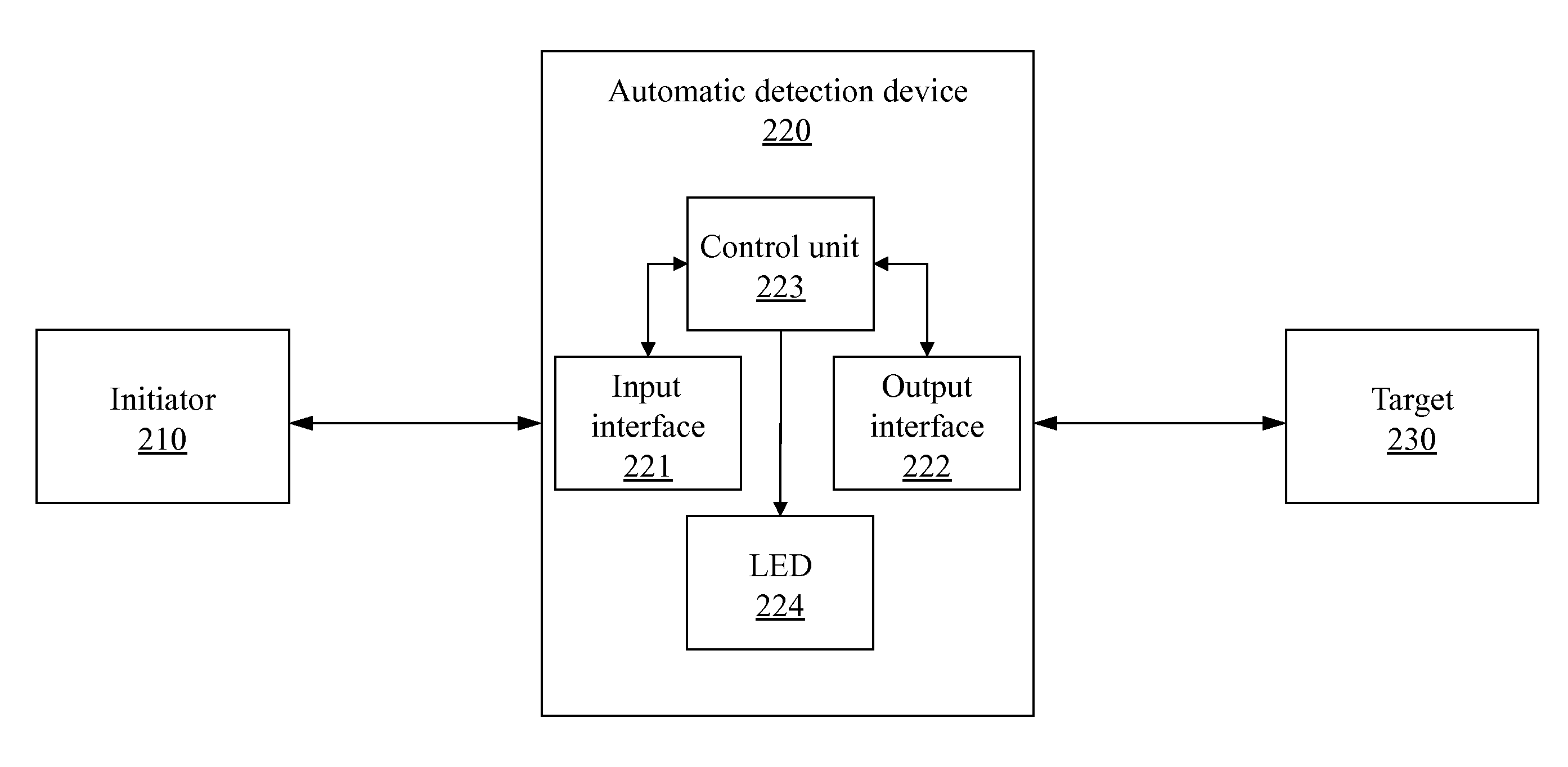
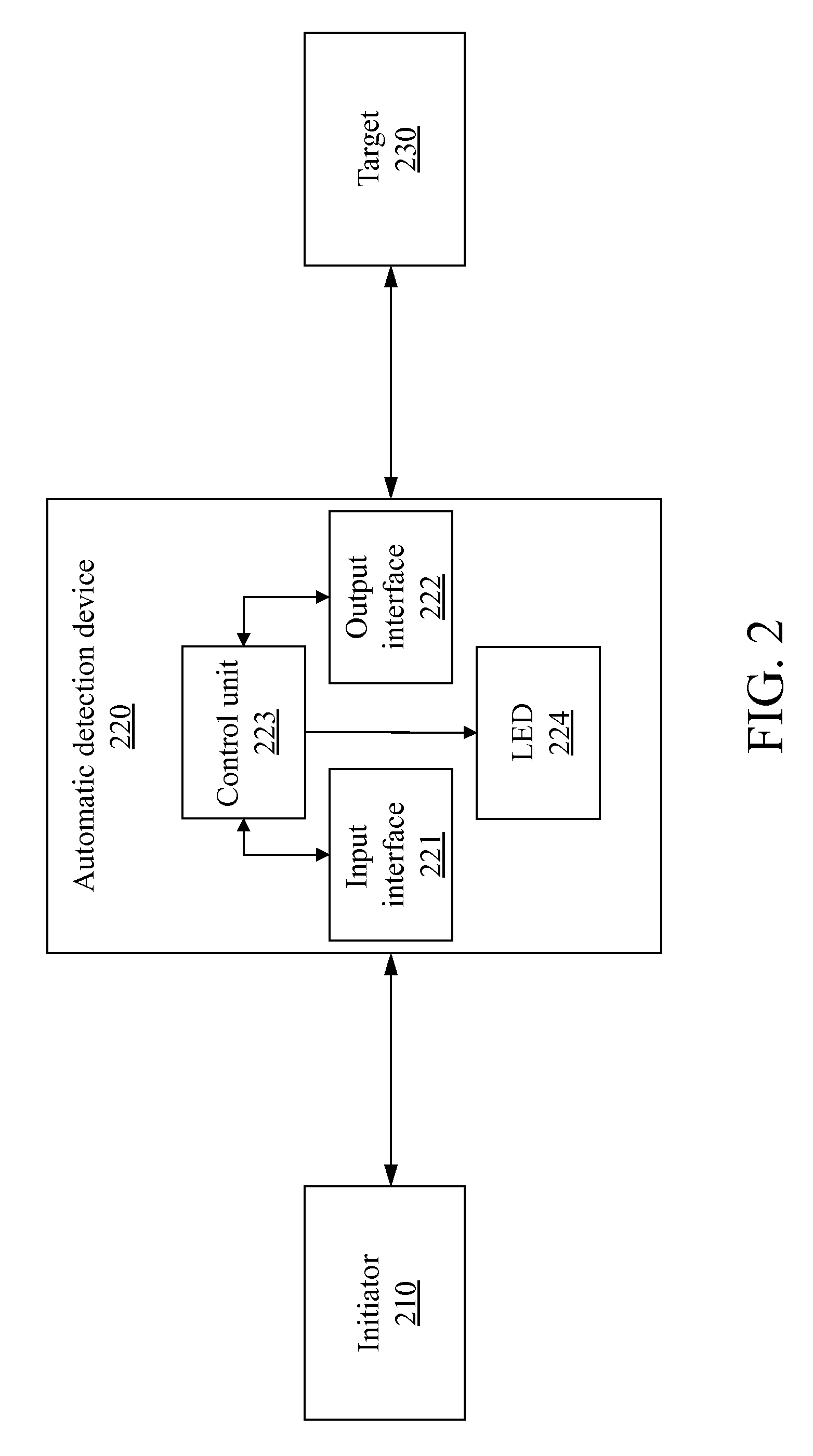
[0025]FIG. 2 is a schematic view of the architecture of one embodiment of the invention.

[0026]An automatic serial signal detecting and transceiving device 220 is electrically connected between an initiator 210 and a target 230. The initiator 210 is a motherboard or a host bus adapter (HBA) of a computer device, and the target 230 may be, but is not limited to, a backplane or another peripheral device with a supporting interface protocol. In one embodiment, the automatic serial signal detecting and transceiving device 220 is physically separate from the target 230. In another embodim...


PUM


Abstract

An automatic serial signal detecting and transceiving device and related system and method are provided for detecting whether a connected initiator unit is using an inter-integrated circuit (I2C) interface protocol or a serial general purpose input / output (SGPIO) interface protocol. The device includes an input interface, connected to the initiator unit, and a control unit. A load pin of the input interface services either the SLoad signal line of an SGPIO bus, or the Reset signal line of an I2C bus. As the device is connected to different initiators, the control unit monitors the load pin for a trigger signal, thereby automatically detecting the interface protocol in use, and processes and transceives data in accordance with the detected interface protocol. The control unit also controls a light-emitting diode (LED) based on the detected interface protocol and data transmitted in accordance with the detected interface protocol.

Description

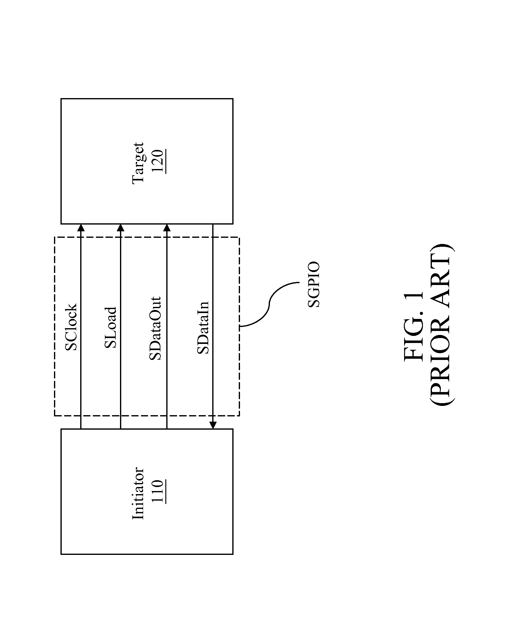
CROSS-REFERENCE TO RELATED APPLICATIONS[0001]This non-provisional application claims priority under 35 U.S.C. §119(a) on Patent Application No(s). 100120905 filed in Taiwan, R.O.C. on Jun. 15, 2011, the entire contents of which are hereby incorporated by reference.BACKGROUND[0002]1. Technical Field[0003]The technical field relates generally to serial data transfer protocols, and more particularly to a device and method for detecting whether a connected device is using an inter-integrated circuit (I2C) interface protocol or a serial general purpose input / output (SGPIO) interface protocol.[0004]2. Related Art[0005]As a consequence of the miniaturization of integrated circuits, the data transfer speed and capacity of storage equipment has grown significantly. To enable faster transfer of data between storage devices, new sequencing technology has replaced the conventional Small Computer Small Interface (SCSI) and Advanced Technology Attachment (ATA) hard drive parallel connection techn...

Claims


Application Information

Patent Timeline
Patent Type & Authority Patents(United States)
IPC IPC(8): G06F13/36G06F13/42
CPCG06F13/42G06F13/4282
Inventor CHANG, PO-CHUNG
Owner INVENTEC CORP
Learn More