
Direct exchange heating/cooling system

a technology of heating/cooling system and direct exchange, which is applied in the direction of domestic cooling apparatus, fluid pressure control, instruments, etc., can solve the problems of excessively high sub-surface ground temperature in the immediate vicinity, and achieve the effects of reducing the ultimate heat load, reducing the heat absorption load, and removing high level heat and excessive hea

Active Publication Date: 2014-09-16
WIGGS B RYLAND
View PDF108 Cites 8 Cited by
  • Summary
  • Abstract
  • Description
  • Claims
  • Application Information

AI Technical Summary

Benefits of technology

The DX systems disclosed herein solve the problem of high pressures during cooling mode by using a supplemental air-source heat exchanger, called HLHD. This device helps to dissipate heat from the system's compressor and prevents premature refrigerant condensation. The HLHD is designed for vapor refrigerant transport and includes check valves to force hot gas through it in the cooling mode. Overall, this improvement makes the DX systems more efficient and practical for geothermal heating and cooling applications.

Problems solved by technology

Excessively high sub-surface ground temperatures in the immediate vicinity of the sub-surface geothermal heat exchange tubing are typically caused by soils / ground with poor heat conductivity, by over-design climatic temperatures, or by system sizing / design error (system under-sizing).
However, if plate heat exchangers are used, it is important that at least one good filter be placed in the refrigerant flow path to the plate heat exchanger, as only a tiny amount of debris can block adequate refrigerant flow through a plate heat exchanger.

Method used


Image

  • Direct exchange heating/cooling system
  • Direct exchange heating/cooling system
  • Direct exchange heating/cooling system

Examples


Embodiment Construction

[0042]The following detailed description provides the best presently contemplated mode. The description is not intended in a limiting sense, and is made solely for the purpose of illustrating the general principles of this disclosure. The various features and advantages of the present disclosure may be more readily understood with reference to the following detailed description taken in conjunction with the accompanying drawings.

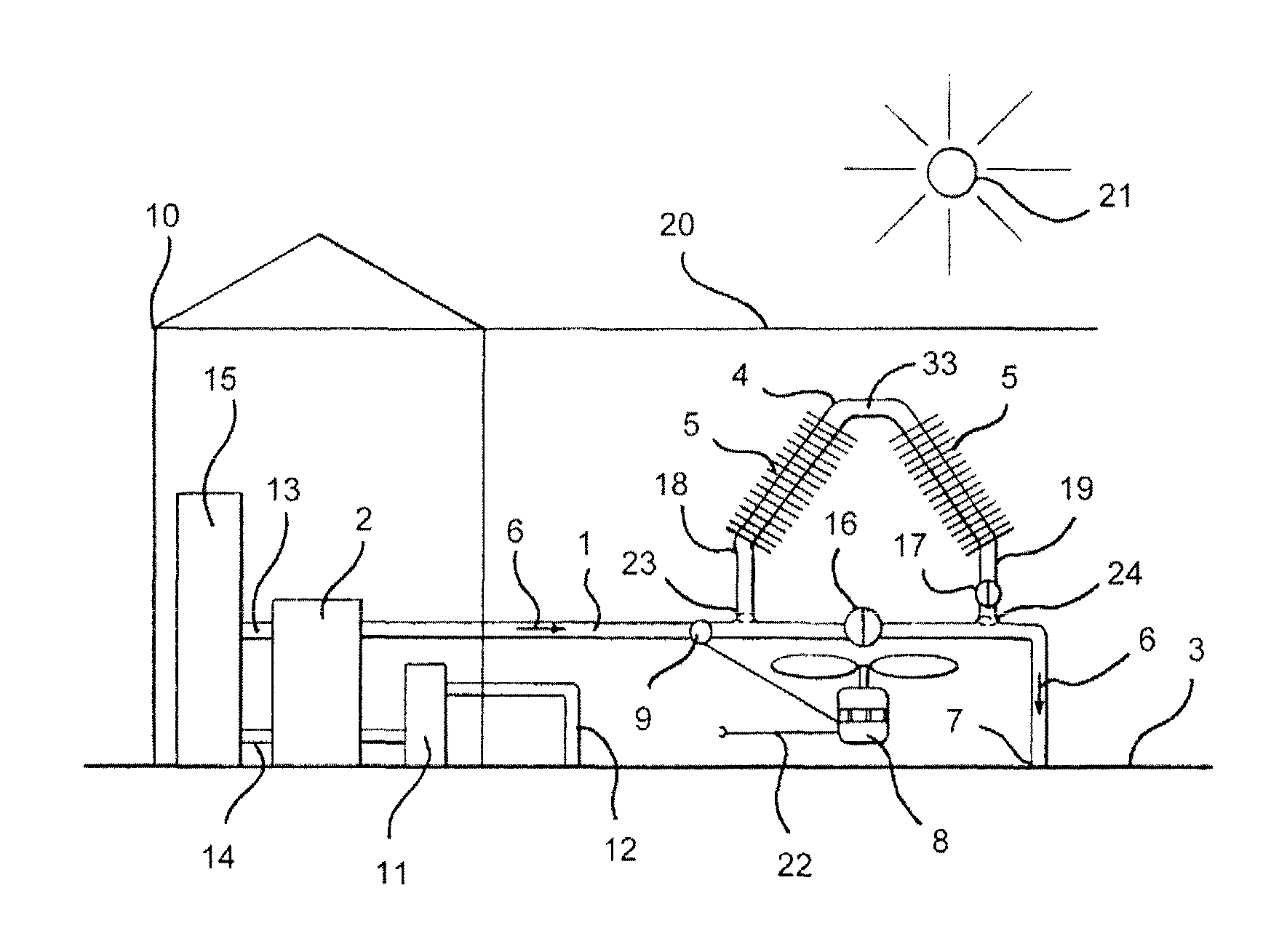
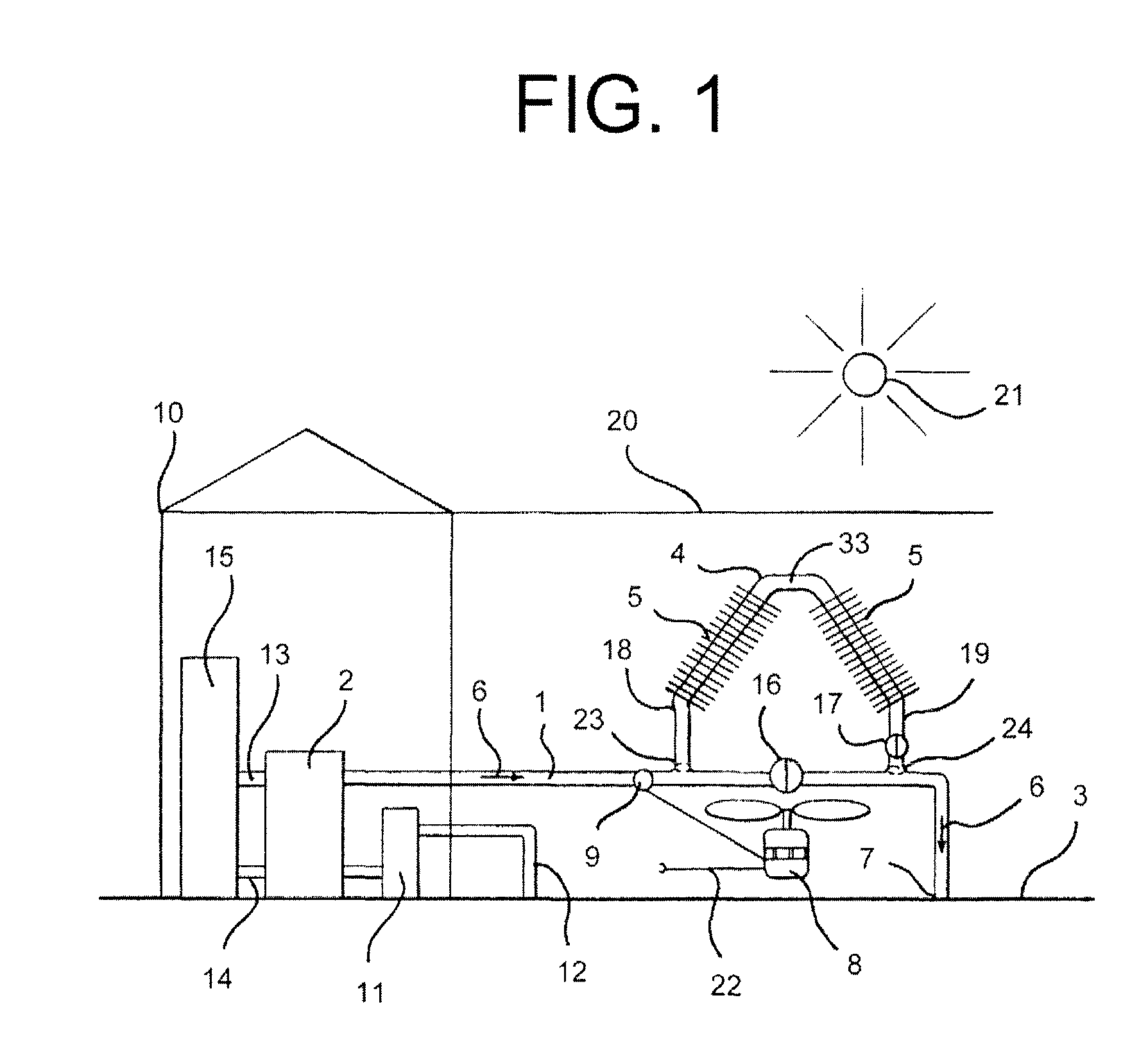
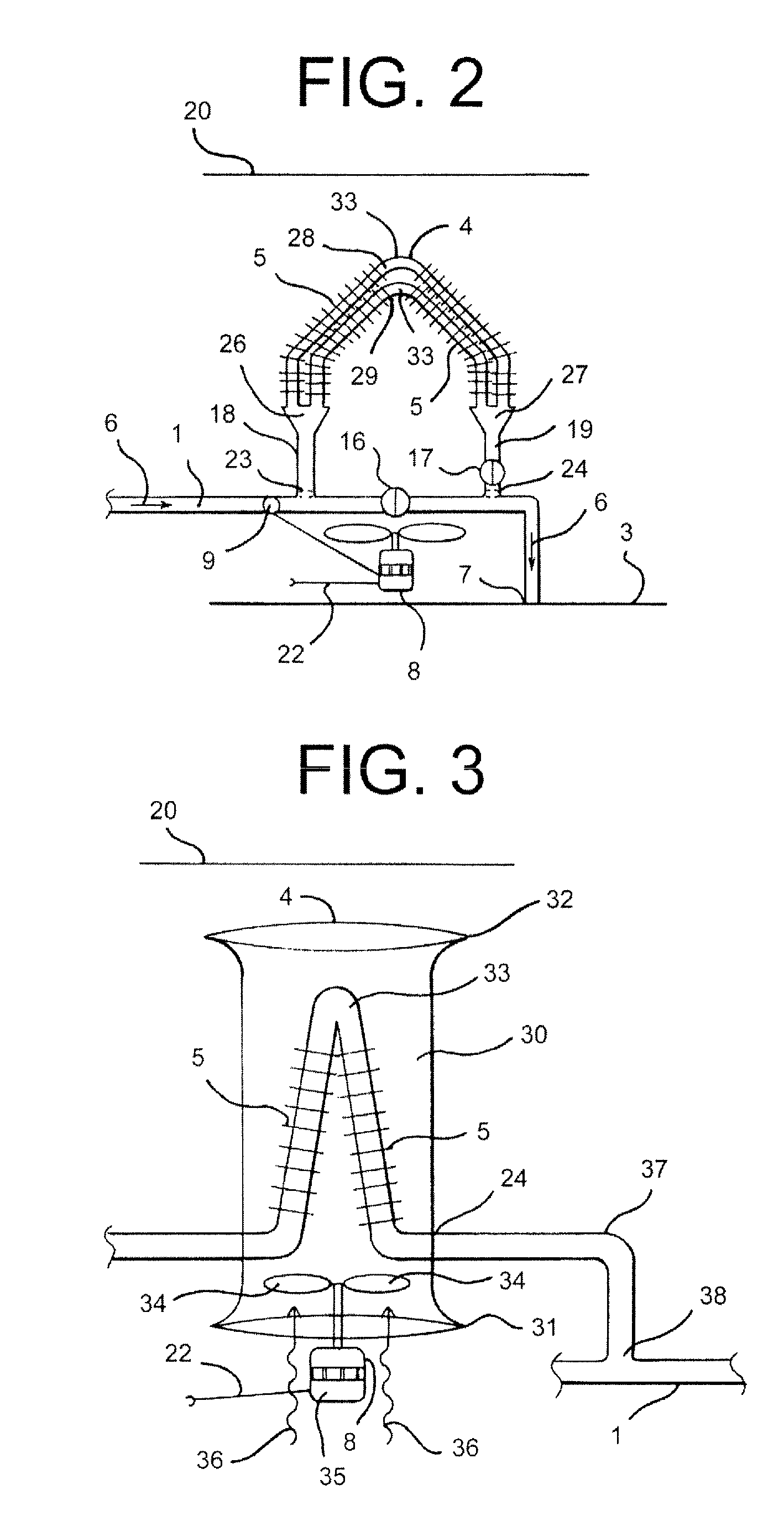
[0043]Referring now to the drawings in detail, where like numerals refer to like parts or elements, FIG. 1 shows a side view of a direct exchange system having a primary vapor / hot gas refrigerant transport line 1 situated between a compressor 2 and the earth's surface 3. The primary transport line 1 is operatively connected to an exterior air-source heat exchange supplement, or high level heat dissipater (HLHD) 4, which includes finned refrigerant transport tubing 5 exposed to the exterior air outside of the interior space. After exiting the HLHD 4, the refr...


PUM


Abstract

A direct exchange heating / cooling system includes a specially designed supplemental air-source heat exchanger (also referred to herein as a High Level Heat Dissipater (“HLHD”). The HLHD is coupled to the primary vapor / hot gas line exiting the system's compressor at a point between the compressor unit and the sub-surface geothermal heat exchange tubing, and is operable only in the cooling mode of system operation. The HLHD includes heat exchange tubing that is sheltered from rain / moisture and has supply and discharge refrigerant transport tubing with relatively equally sized interior diameters, designed solely for mostly vapor (as opposed to liquid) refrigerant transport. The HLHD incorporates at least two check valves, or the like, so as to force hot compressor discharge gas through the HLHD in the cooling mode, and so as to prohibit geothermally warmed refrigerant gas flow through the HLHD in the heating mode. The HLHD has specially designed heat exchangers and may optionally include a fan.

Description

CROSS-REFERENCE TO RELATED APPLICATION[0001]The present application claims the benefit of U.S. Provisional Application No. 60 / 949,910 filed on Jul. 16, 2007.FIELD OF THE DISCLOSURE[0002]The present disclosure relates to a geothermal “direct exchange” (“DX”) heating / cooling system, comprising various design improvements.BACKGROUND OF THE DISCLOSURE[0003]Geothermal ground source / water source heat exchange systems typically use fluid-filled closed loops of tubing buried in the ground, or submerged in a body of water, so as to either absorb heat from, or to reject heat into, the naturally occurring geothermal mass and / or water surrounding the buried or submerged fluid transport tubing. The tubing loop is extended to the surface and is then used to circulate the naturally warmed or cooled fluid to an interior air heat exchange means.[0004]Common and older design geothermal water-source heating / cooling systems typically circulate, via a water pump, a fluid comprised of water (or water wit...

Claims


Application Information

Patent Timeline
Patent Type & Authority Patents(United States)
IPC IPC(8): F24J3/08G05D15/00G05D16/00F25D23/12G05D23/00
CPCF28B1/06F24J3/08F25B13/00F25B30/06F25B2313/0252F25B2313/0254F25B2500/01Y02E10/10F24T10/10
Inventor WIGGS, B., RYLAND
Owner WIGGS B RYLAND
Learn More