Structure and fabrication of a microscale flow-rate/skin friction sensor

a micro-scale flow-rate/skin friction sensor technology, applied in the direction of force measurement, printed circuit manufacturing, instruments, etc., can solve the problems of low efficiency, inability to direct the measurement of fluctuating shear stress, time-consuming, and increase fuel consumption, so as to improve efficiency and reduce fabrication cost and time. , the effect of improving efficiency

Active Publication Date: 2014-09-16
UNIV OF FLORIDA RES FOUNDATION INC
View PDF4 Cites 6 Cited by
  • Summary
  • Abstract
  • Description
  • Claims
  • Application Information

AI Technical Summary

Benefits of technology

[0008]In a further embodiment, damping and cavity compliance can be used to minimize out-of-plane sensitivity, which can be achieved by moving the cut-on frequency of out-of-plane signal beyond the desired bandwidth for in-plane motion. The cavity stiffness may also be used for minimizing out of plane sensitivity, as it lowers the overall out-of-plane compliance.
[0009]According to an embodiment, sensitivity of the subject sensor can be improved by incorporating additional capacitance between tethers, the floating element and the substrate.
[0011]The dissimilar / asymmetric comb fingers of sensor embodiments can be fabricated using bulk micromachining or surface micromachining in a single mask process. In addition, the micromachining can be used to achieve flush mounting of sensor for flow measurements. Backside cavity and damping incorporated in embodiments of the subject sensor can effectively lower out-of-plane sensitivity.
[0014]Embodiments of the present invention can be fabricated using a two mask fabrication process. The two mask fabrication process can significantly lower fabrication cost and time, improving efficiency.

Problems solved by technology

In engine applications, wall shear stress can lower efficiency and increase fuel consumption.
However, despite several research efforts, time-accurate, continuous, direct measurement of fluctuating shear stress has been elusive due to stringent spatial and temporal resolution requirements.
However, the prior sensors have shown limited performance in terms of sensitivity drift, and insufficient dynamic range, bandwidth, and / or minimum detectable signal (MDS).

Method used


Image

  • Structure and fabrication of a microscale flow-rate/skin friction sensor
  • Structure and fabrication of a microscale flow-rate/skin friction sensor
  • Structure and fabrication of a microscale flow-rate/skin friction sensor

Examples


Embodiment Construction

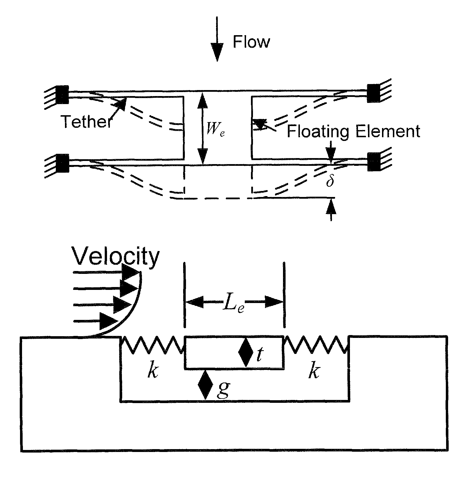
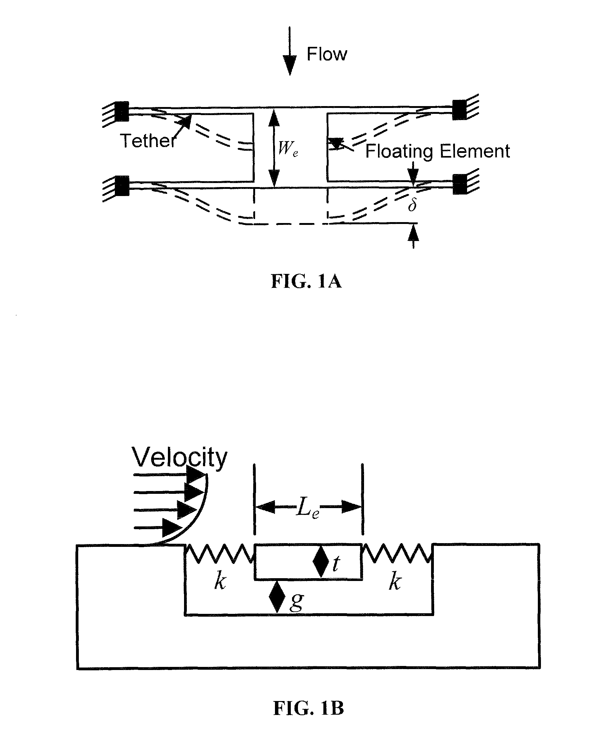
[0038]Embodiments of the present invention provide a flow-rate / skin friction / shear stress sensor. In one embodiment, the shear stress sensor can be a MEMS-based floating element shear stress sensor. In a further embodiment, the floating element shear stress sensor can utilize a differential capacitive transduction scheme.

[0039]FIGS. 1A and 1B show schematic representations of a floating element sensor. Referring to FIG. 1A, tethers serve as restoring springs. In addition, the shear stress deflects the floating element laterally while a displacement transducer provides a desired output. A number of transduction options are available, including capacitive, optical, piezoresistive, and piezoelectric.

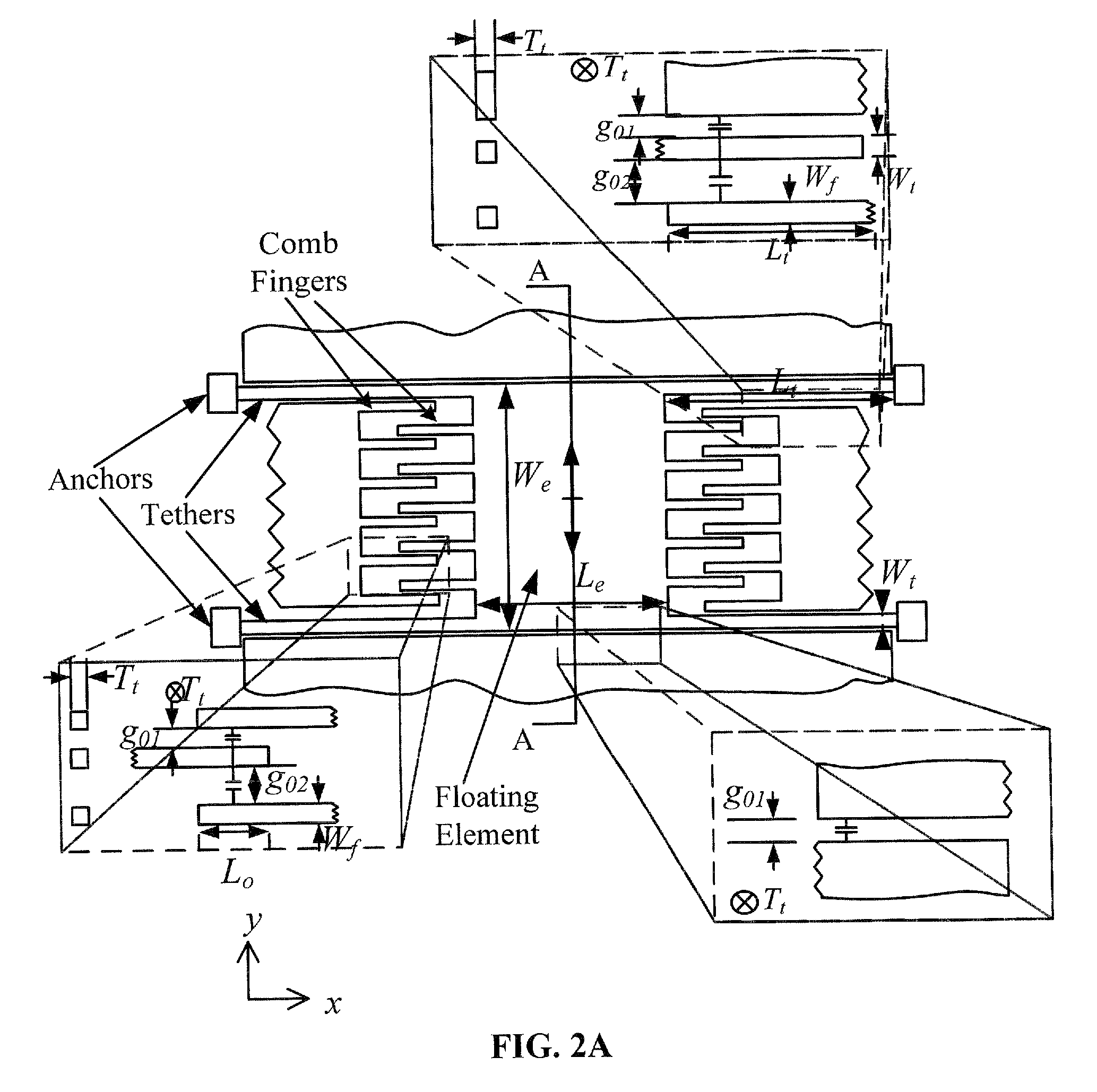
[0040]According to embodiments of the present invention, the sensor structure can include interdigitated variable-gap capacitive comb fingers on a floating element. The interdigitated variable-gap capacitive comb fingers can produce an electrical output proportional to the deflection due to...


PUM

PropertyMeasurementUnit
frequency responseaaaaaaaaaa
bias voltagesaaaaaaaaaa

Abstract

A floating element shear sensor and method for fabricating the same are provided. According to an embodiment, a microelectromechanical systems (MEMS)-based capacitive floating element shear stress sensor is provided that can achieve time-resolved turbulence measurement. In one embodiment, a differential capacitive transduction scheme is used for shear stress measurement. The floating element structure for the differential capacitive transduction scheme incorporates inter digitated comb fingers forming differential capacitors, which provide electrical output proportional to the floating element deflection.

Description

GOVERNMENT SUPPORT[0001]This invention was made with government support under award number NNX07AB27A awarded by NASA. The government has certain rights in the invention.CROSS REFERENCE TO RELATED APPLICATION[0002]This application is the U.S. national stage application of International Application Serial No. PCT / US2009 / 037158, filed Mar. 13, 2009, which is hereby incorporated by reference in its entirety, including all figures, tables and drawings.BACKGROUND OF THE INVENTION[0003]The measurement of time-resolved wall shear stress is an important aspect for both fundamental scientific studies and applied aerodynamic applications. In general, wall shear stress is the friction between a moving fluid and adjacent surface. Wall shear can also be referred to as skin friction, which can be used to determine drag, transition, and flow separation. In engine applications, wall shear stress can lower efficiency and increase fuel consumption. In particular, quantitative measurement of wall shea...

Claims


Application Information

Patent Timeline
Patent Type & Authority Patents(United States)
IPC IPC(8): G01L1/00G01B7/16
CPCG01N13/00G01N2013/0216Y10T29/49156
Inventor CHANDRASEKHARAN, VIJAYSELLS, JEREMYSHEPLAK, MARKARNOLD, DAVID P.
Owner UNIV OF FLORIDA RES FOUNDATION INC
Why Eureka
Try Eureka