
Fluid treatment system comprising radiation source module and cooling means

a radiation source module and treatment system technology, applied in specific water treatment objectives, disinfection, energy-based chemical/physical/physicochemical processes, etc., can solve the problems of reducing the efficiency of lamps, so as to facilitate the maintenance of discharge gas, reduce the cost, and reduce the effect of oxidation

Inactive Publication Date: 2014-09-16
KONINK PHILIPS ELECTRONICS NV +1
View PDF12 Cites 10 Cited by
  • Summary
  • Abstract
  • Description
  • Claims
  • Application Information

AI Technical Summary

Benefits of technology

The invention is a UV source that can effectively cool down the heat generated by the discharge process, using a fluid flow within the lamp. This makes it easier to maintain the optimal temperature for the discharge gas. The UV source is a dielectric barrier discharge lamp, which is a cost-effective and efficient choice for high-powered applications such as water treatment. Baffling means are used to guide the process fluid into and out of the lamp. Overall, this UV source design provides improved cooling efficiency and reduced costs for high-powered applications.

Problems solved by technology

As a lamp run at a high power density has a higher internal temperature than a lamp run at a lower power, there is the problem that during use the electrodes and discharge gas can be overheated.
Overheating the electrodes alters the wavelength of the emitted radiation, reduces the lamp efficiency and can lead to degradation of the electrodes and the dielectric material, reducing the useful lifetime of the lamp.
This results in a broader spectrum of emitted radiation, which can have undesired consequences on fluid treatment processing.
Thus, a significant problem in the art is how to overcome these differences in temperatures locally within the devices, and how to keep the lamp cool enough to efficiently generate UV or VUV radiation.
Under the rough conditions in a water treatment plant, such lamp may provide a safety hazard, if the electrically insulated tubing is not carefully protected against unintended breakage.

Method used


Image

  • Fluid treatment system comprising radiation source module and cooling means
  • Fluid treatment system comprising radiation source module and cooling means

Examples


Embodiment Construction

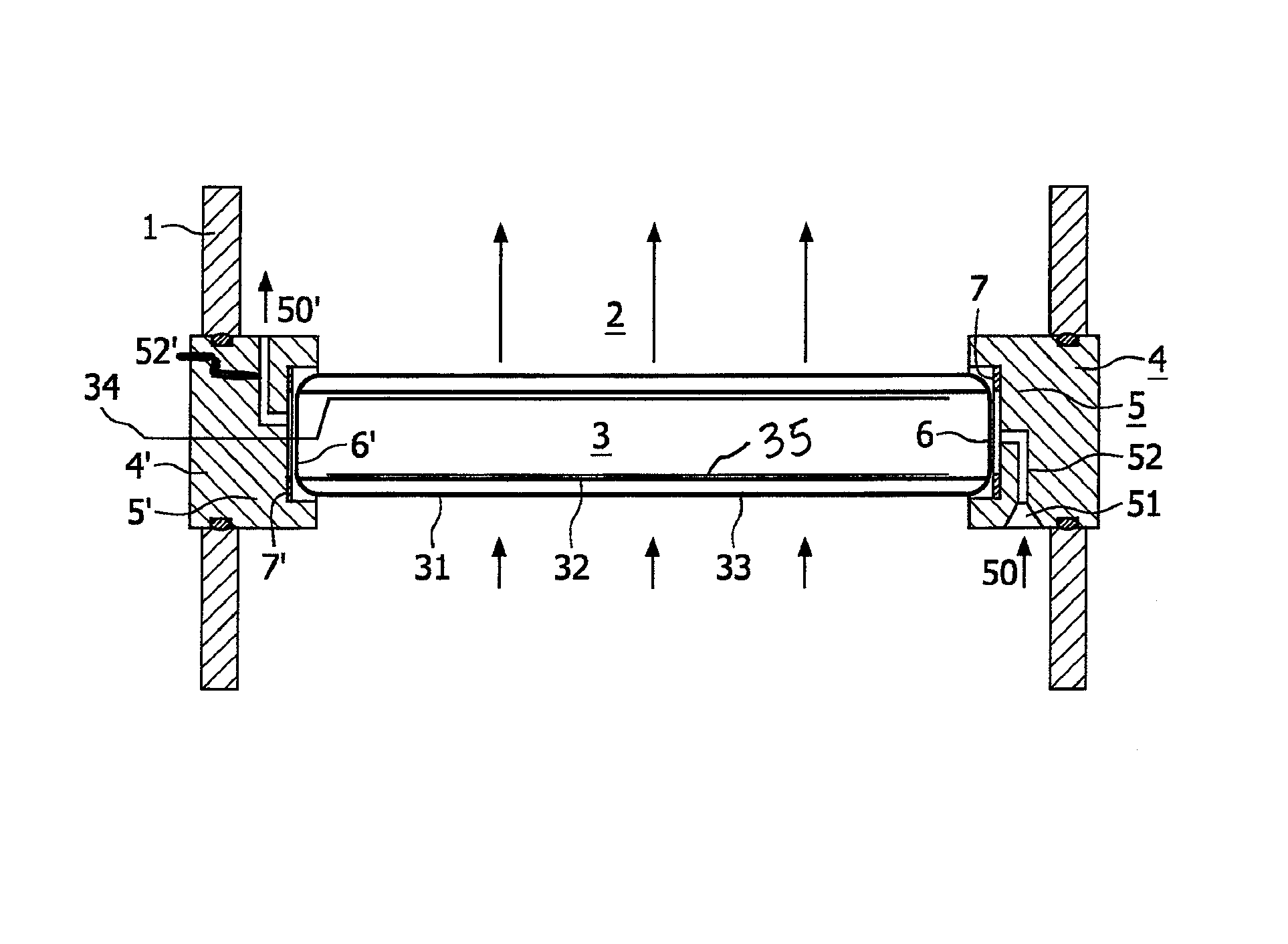
[0032]The present invention provides a fluid treatment system comprising a housing for receiving a flow of fluid, the housing comprising a fluid inlet, a fluid outlet, an irradiation zone disposed between the fluid inlet and the fluid outlet, and at least one radiation source module comprising a radiation source to irradiate the fluid.

[0033]As is known to those of skill in the art, the dosage of radiation received by the fluid is the product of the radiation intensity and the exposure time. The intensity of the radiation varies with the square of the distance the radiation passes through, but the exposure time varies linearly with the fluid flow velocity. Accordingly, it is desired to maintain the fluid to be treated as close as possible to the radiation sources.

[0034]To this aim, the at least one radiation source module includes at least one radiation source mounted within a submersible frame. During operation the frame enclosing the radiation source is immersed into the fluid to b...


PUM

PropertyMeasurementUnit
wavelengthsaaaaaaaaaa

Abstract

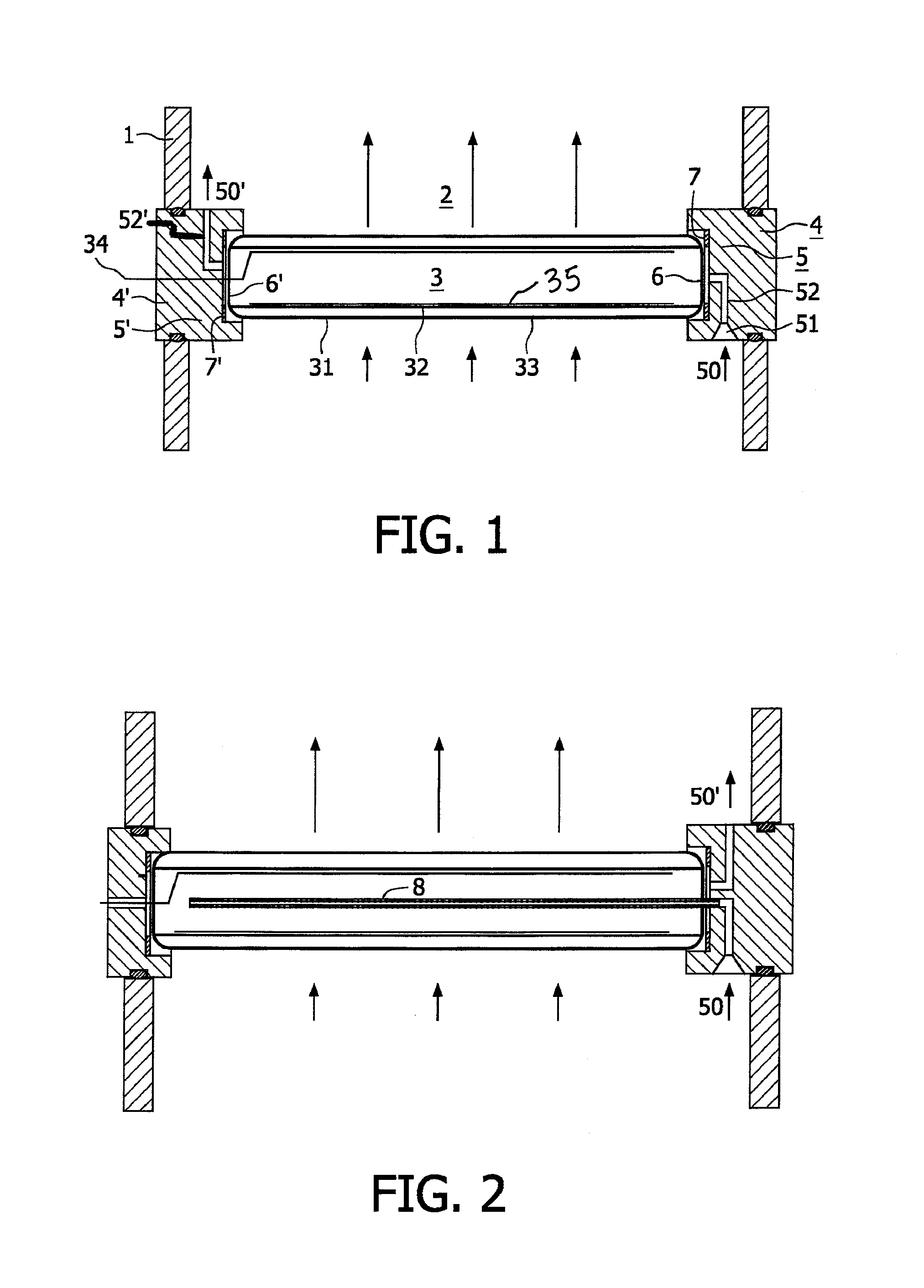
In a fluid treatment system includes a housing with fluid inlet and outlet for a process fluid, an irradiation zone disposed between the fluid inlet and fluid outlet, and at least one radiation source module with a radiation source having a discharge vessel with outer and inner wall. The inner wall encloses an internal volume with at least one opening and an internal electrode for igniting and maintaining a discharge. The radiation source module also includes a submersible frame with a guide to guide the process fluid into and out of the internal volume of the radiation source. The dissipation of the heat generated by the discharge in the discharge gap via a fluid flow in the internal volume of the lamp and in contact with the internal electrode is substantially more effective than dissipation via a cooling channel separated from the internal electrode. It is therefore substantially easier to maintain the discharge at an approximately optimal temperature.

Description

FIELD OF THE INVENTION[0001]The invention relates to a fluid treatment system for treating a fluid by exposing it to high-energy radiation. The fluid treatment system comprises a housing for receiving a flow of fluid with a fluid inlet, a fluid outlet, an irradiation zone disposed between the fluid inlet and the fluid outlet, and at least one radiation source module disposed in the irradiation zone. The at least one radiation source module comprises at least one high-energy radiation sources and cooling means for said high-energy radiation source.[0002]As a radiation source a dielectric barrier discharge lamp is especially contemplated.BACKGROUND OF THE INVENTION[0003]For fluid treatment systems using exposition to high-energy radiation, especially high-energy ultraviolet radiation, there are various applications such as, for example, sterilization, curing of lacquers and synthetic resins, flue-gas purification, destruction and synthesis of special chemical compounds.[0004]Further a...

Claims


Application Information

Patent Timeline
Patent Type & Authority Patents(United States)
IPC IPC(8): A61L2/10C02F1/32
CPCC02F1/32A61L2/10C02F1/325C02F2303/04
Inventor SCHIENE, WOLFGANGGREUEL, GEORG
Owner KONINK PHILIPS ELECTRONICS NV
Learn More