Method for regeneration of exhaust gas treatment catalyst, and exhaust gas treatment cataylst produced using the method

a technology of exhaust gas treatment and catalyst, which is applied in the direction of physical/chemical process catalysts, other chemical processes, separation processes, etc., can solve the problems of lowering denitration performance and difficult exhaust gas flow into the holes, and achieves high-strength surface, high sintering efficiency, and sufficient wear resistance

Active Publication Date: 2014-09-16
MITSUBISHI POWER LTD
View PDF19 Cites 0 Cited by
  • Summary
  • Abstract
  • Description
  • Claims
  • Application Information

AI Technical Summary

Benefits of technology

[0041]In the method of regenerating an exhaust gas treatment catalyst according to the present invention, a surface of a base is coated with a slurry liquid of a crushed newly-made exhaust gas treatment catalyst, and calcined at a higher temperature than that during production of the crushed newly-made exhaust gas treatment catalyst. This can surely increase the degree of sintering a surface of a regenerated exhaust gas treatment catalyst. Hence, an exhaust gas treatment catalyst according to the present invention has a high-strength surface and is capable of demonstrating a sufficient wear resistance while keeping a sufficient denitration performance. Thus, the exhaust gas treatment catalyst according to the present invention is continuously usable over a long period (approximately 20,000 to 30,000 hours).

Problems solved by technology

Additionally, the fly ash itself is partially deposited inside the holes, and gradually makes it hard for exhaust gas to flow into the holes.
Eventually, the fly ash completely blocks and clogs the holes, accordingly lowering the denitration performance.

Method used


Image

  • Method for regeneration of exhaust gas treatment catalyst, and exhaust gas treatment cataylst produced using the method
  • Method for regeneration of exhaust gas treatment catalyst, and exhaust gas treatment cataylst produced using the method
  • Method for regeneration of exhaust gas treatment catalyst, and exhaust gas treatment cataylst produced using the method

Examples


main embodiment

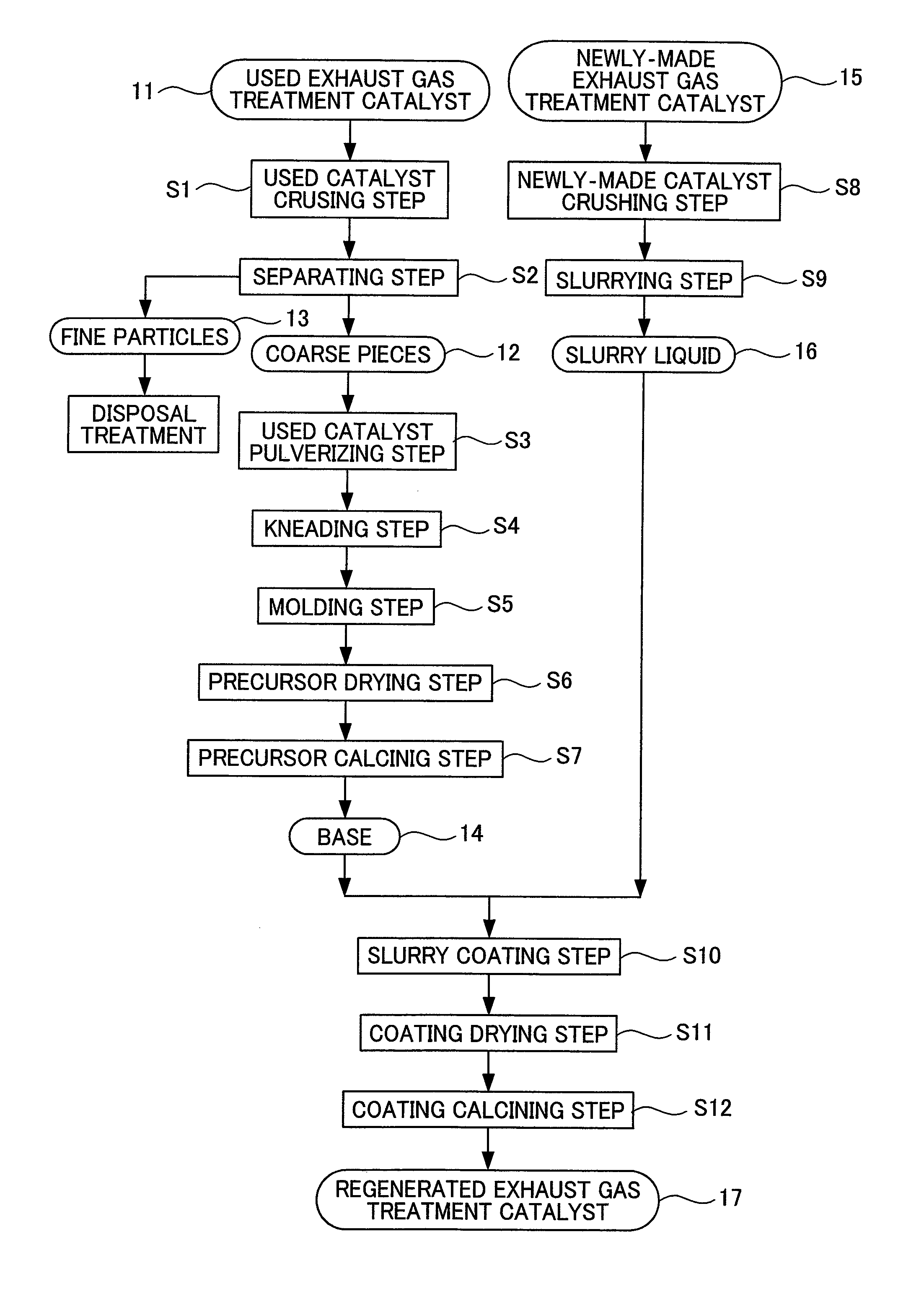
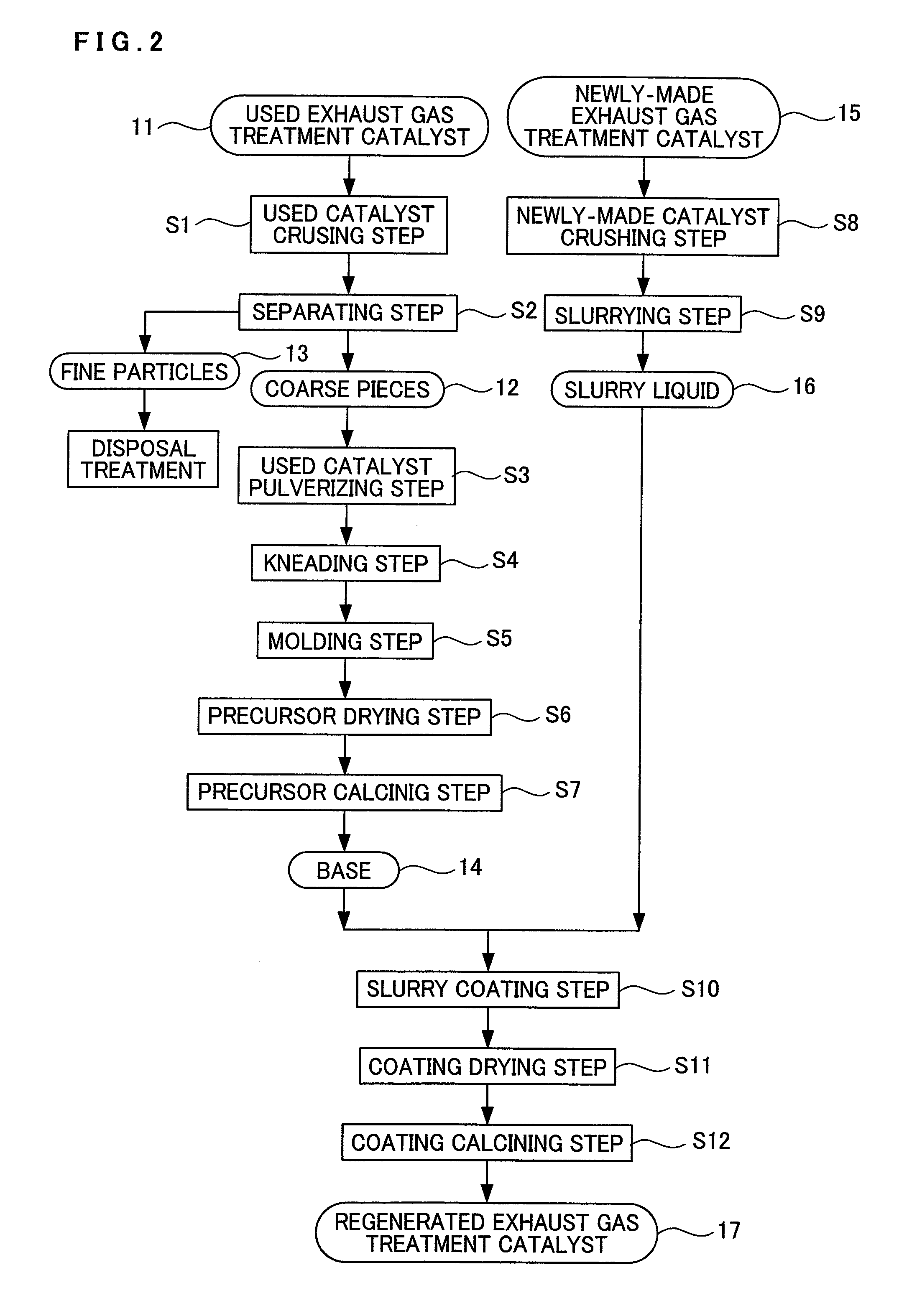
[0046]A main embodiment of a method of regenerating an exhaust gas treatment catalyst according to the present invention and an exhaust gas treatment catalyst obtained by the method will be described on the basis of FIGS. 1 and 2.

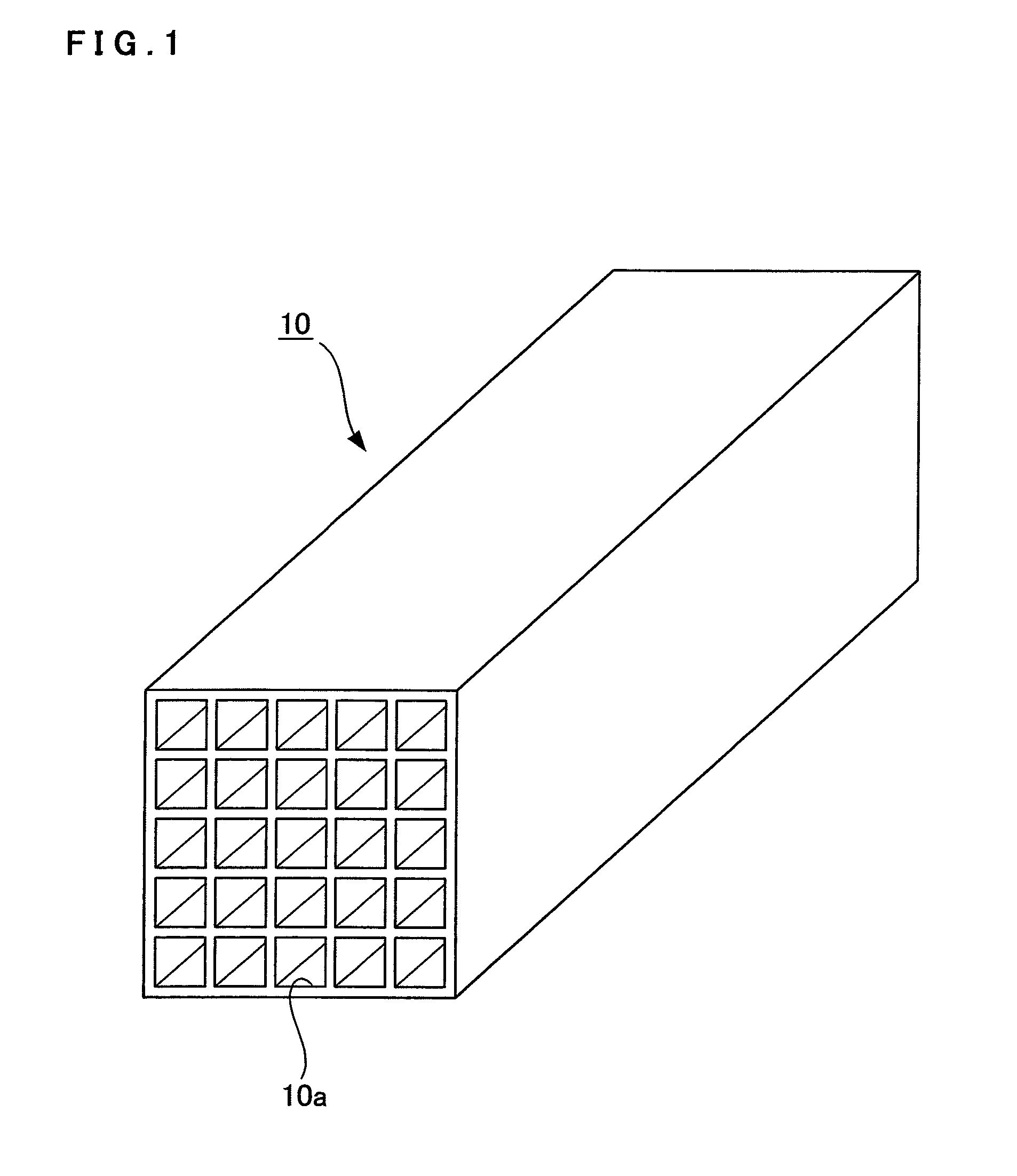
[0047]As shown in FIG. 1, an exhaust gas treatment catalyst 10 according to the present embodiment is obtained by the following process: titanium oxide (TiO2) as a main component and further tungsten oxide (WO3), vanadium oxide (V2O5), and the like are kneaded together with a binder, molded into a honeycomb shape so as to have multiple holes 10a, and calcined.

[0048]Such an exhaust gas treatment catalyst 10 is installed in a discharge line for exhaust gas from equipment, such as a coal-fired boiler, for burning coal. A reducing agent such as ammonia (NH3) is flowed into the holes 10a together with the exhaust gas to bring the nitrogen oxide (NOx) in the exhaust gas and the reducing agent into contact with the wall surfaces of the holes 10a. This enables the ...


PUM

PropertyMeasurementUnit
threshold sizeaaaaaaaaaa
temperatureaaaaaaaaaa

Abstract

A regenerated exhaust gas treatment catalyst (17) can be produced by coarsely grinding a used exhaust gas treatment catalyst (11); separating a coarsely ground material into coarse pieces (12) and a fine powder (13); finely grinding the coarse pieces (12); kneading the fine powder together with other raw materials, molding a kneaded material, and drying and burning a molded material to produce a base material (14); grinding a fresh exhaust gas treatment catalyst (15); forming a slurry solution of the ground product of the fresh exhaust gas treatment catalyst (15); coating the surface of the base material (14) with the slurry solution (16); and drying the base material (14) that has been coated with the slurry solution (16) and burning the base material (14) at a temperature higher than the burning temperature employed in the production of the exhaust gas treatment catalyst (15).

Description

TECHNICAL FIELD[0001]The present invention relates to a method of regenerating an exhaust gas treatment catalyst having ash adhering to a surface thereof and an exhaust gas treatment catalyst obtained by the method. The present invention is extremely effective particularly when employed to regenerate an exhaust gas treatment catalyst, mainly containing titanium oxide, for removing nitrogen oxide in exhaust gas from burned coal.BACKGROUND ART[0002]A discharge line for exhaust gas from equipment, such as, for example, a coal-fired boiler or the like, in which coal is burnt is provided with an exhaust gas treatment catalyst for treating nitrogen oxide (NOx) in the exhaust gas. The exhaust gas treatment catalyst is obtained by the following process: titanium oxide (TiO2) as a main component, and further tungsten oxide (WO3), vanadium oxide (V2O5), and the like are kneaded together with a binder, molded into a honeycomb shape so as to have multiple holes, and calcined. A reducing agent s...

Claims


Application Information

Patent Timeline
Patent Type & Authority Patents(United States)
IPC IPC(8): B01J38/72B01J38/02B01D53/94B01J21/06B01J23/30B01J23/92B01J35/02B01J37/00B01J37/02B01J37/06B01J37/08
CPCB01D53/9418B01J21/063B01J35/04B01J23/92B01J37/06B01J35/023B01J37/0009B01J37/0036B01J23/30B01J37/0215B01D2255/20707B01D2251/2062B01J37/08B01D2255/9202B01J38/48B01D53/94B01D53/96
Inventor OBAYASHI, YOSHIAKIKIYOSAWA, MASASHIDEMOTO, MASANORI
Owner MITSUBISHI POWER LTD
Why Eureka
Try Eureka