
Hybrid drive apparatus

a hybrid drive and drive technology, applied in the direction of fluid gearings, gas pressure propulsion mountings, electric devices, etc., can solve the problems of significant increase in manufacturing costs, deterioration of driveability, and deterioration of driving comfort and driving ease, so as to suppress the deterioration of driveability and internal combustion

Inactive Publication Date: 2014-09-16
AISIN AW CO LTD +1
View PDF97 Cites 9 Cited by
  • Summary
  • Abstract
  • Description
  • Claims
  • Application Information

AI Technical Summary

Benefits of technology

The patent aims to reduce costs of a hybrid drive apparatus by using a mechanical oil pump instead of a separate hydraulic pressure source. However, this may cause vibration and reduced driving comfort when starting the vehicle in the electric drive mode because of the high torque transmitted through the input clutch. The technical effect of this patent is to maintain good driving behavior when starting a vehicle in the electric mode.

Problems solved by technology

However, manufacturing cost significantly increases when the apparatus is separately provided with a hydraulic pressure source such as the electric oil pump for disengaging the input clutch as in the apparatus of Japanese Patent Application Publication No.
If the internal combustion engine rotates in this way, when the vehicle starts in the electric drive mode, driveability (driving comfort and ease of driving) may deteriorate due to occurrence of vibration, and so forth.

Method used


Image

  • Hybrid drive apparatus
  • Hybrid drive apparatus
  • Hybrid drive apparatus

Examples


Embodiment Construction

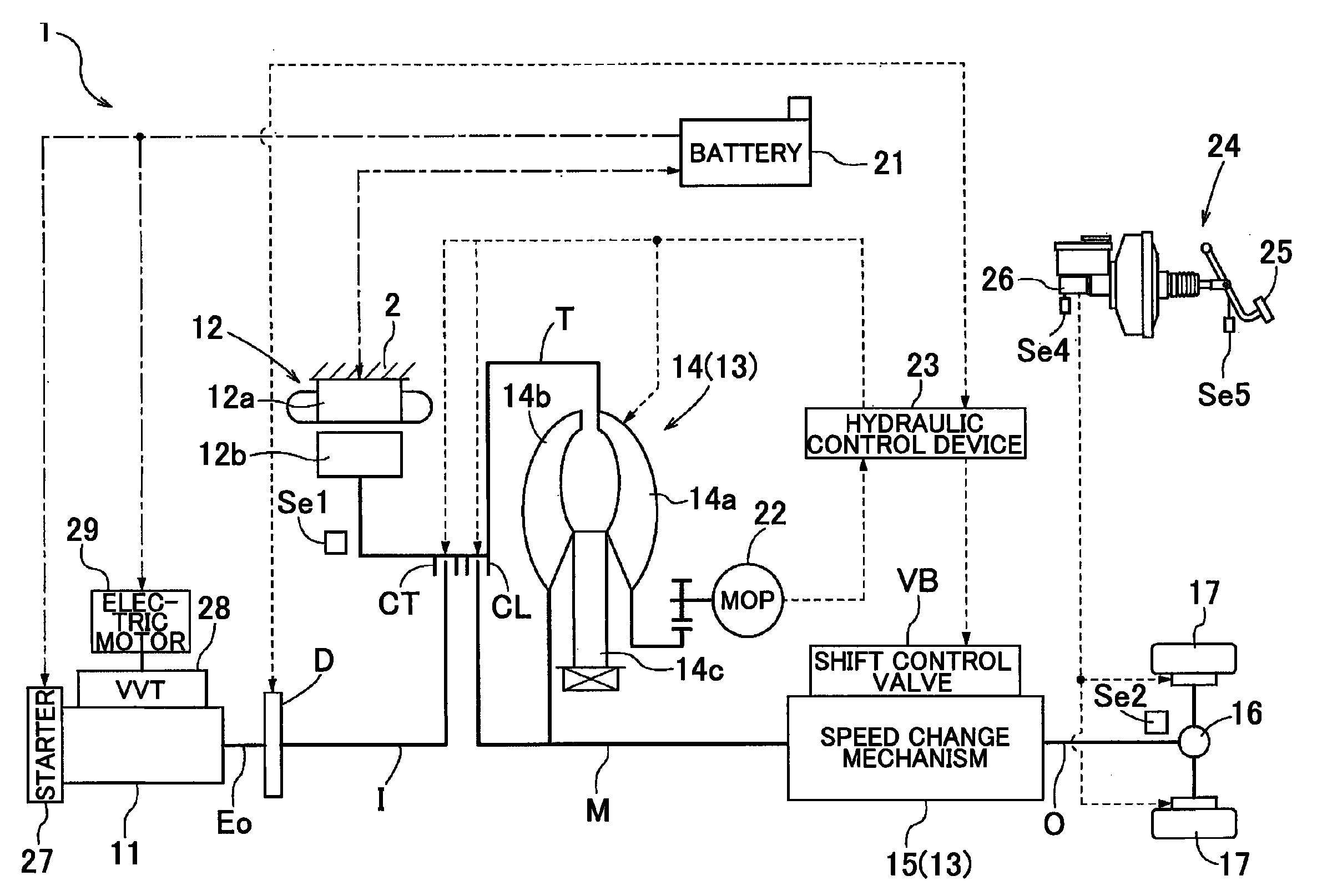
[0041]An embodiment of a hybrid drive apparatus according to the present invention will be described with reference to the accompanying drawings. A hybrid drive apparatus 1 is a drive apparatus for a hybrid vehicle that uses, as a source of vehicle driving force, one or both of an internal combustion engine 11 and a rotary electric machine 12. The hybrid drive apparatus 1 is structured as a so-called one-motor parallel type hybrid drive apparatus.

[0042]As shown in FIG. 1, the hybrid drive apparatus 1 according to the present embodiment is provided with a drive transmission member T that is drivingly connected to the rotary electric machine 12 and drivingly connected via an input clutch CT to the internal combustion engine 11, a transmission device 13 that transmits rotation of the drive transmission member T to an output shaft O at a changed speed, and a mechanical oil pump 22 that is driven by the drive transmission member T. The hybrid drive apparatus 1 is also provided with a con...


PUM


Abstract

A hybrid drive apparatus includes an input member that is drivingly connected to a rotary electric machine and drivingly connected via an input clutch to an internal combustion engine, an output member that is drivingly connected to the input member and transmits rotation of the input member to wheels, and a control device that controls the rotary electric machine. The control device is capable of performing valve opening / closing phase control that advances or retards opening / closing phases of valve elements provided in the internal combustion engine via a valve opening / closing phase adjusting mechanism and, with the internal combustion engine in a stopped state before starting a vehicle, advances the opening / closing phases of the valve elements to bring the opening / closing phases of the valve elements into an advanced phase state relative to predetermined reference phases, thus starting the vehicle with torque of the rotary electric machine in the advanced phase state.

Description

INCORPORATION BY REFERENCE[0001]The disclosure of Japanese Patent Application No. 2010-049193 filed on Mar. 5, 2010, including the specification, drawings and abstract is incorporated herein by reference in its entirety.BACKGROUND OF THE INVENTION[0002]The present invention relates to a hybrid drive apparatus provided with an input member that is drivingly connected to a rotary electric machine and drivingly connected via an input clutch to an internal combustion engine, an output member that is drivingly connected to the input member and transmits rotation of the input member to wheels, and a control device that controls at least the rotary electric machine.DESCRIPTION OF THE RELATED ART[0003]As a hybrid drive apparatus provided with an input member that is drivingly connected to a rotary electric machine and drivingly connected via an input clutch to an internal combustion engine, an output member that is drivingly connected to the input member and transmits rotation of the input ...

Claims


Application Information

Patent Timeline
Patent Type & Authority Patents(United States)
IPC IPC(8): B60W10/02B60W10/04B60K6/387B60K6/48B60K6/547B60K17/02B60L50/16B60W10/06B60W10/08B60W10/30B60W20/00F02D13/02F02D29/02F16D13/52F16D25/0638
CPCY10T477/32B60L3/0092B60W20/00B60W10/026B60L7/10Y10T477/75B60L11/14Y10T477/78B60L3/0023B60K6/387Y02T10/7077B60L7/24B60W10/08B60W30/18027B60W10/06B60W10/02B60L2270/145Y02T10/6221B60K6/48B60W30/192Y02T10/6286Y02T10/70Y10T477/73B60L50/16Y02T10/62Y02T10/7072B60W20/40
Inventor SUYAMA, DAIKIKAMIYA, TOSHIHIKO
Owner AISIN AW CO LTD
Learn More