System and method for fiber magneto-optic detection

a fiber magneto-optic and detection system technology, applied in the field of optical applications, can solve the problems of inaccuracy in measurement, affecting optical characteristics, and measurement precision that may not meet the application requirements, and achieve the effect of improving the measurement precision of the system and eliminating the influence of measuremen

Inactive Publication Date: 2014-09-23
SIEYUAN ELECTRIC CO LTD
View PDF8 Cites 2 Cited by
  • Summary
  • Abstract
  • Description
  • Claims
  • Application Information

AI Technical Summary

Benefits of technology

[0006]The present invention aims to provide a fiber magneto-optic detection system and method thereof, which utilizes a real-time correction mode to eliminate the influence of the environmental factors so as to obtain proper measurement data, etc.
[0017]According to the present invention, a reference device is provided in the measurement system. By virtue of the reference magnetic field signal generated by the reference device, the measured signals can be corrected so as to eliminate the influence on measurement caused by the environmental factors and to obtain proper measurement data, improving the measurement precision of the system.

Problems solved by technology

These affections cause the inaccuracy in measurement, such that the precision of measurement may not meet the application requirement.
Especially, the inventor recognizes that when some material such as garnet crystal is used as a magneto-optic medium to measure the magnetic field, the microcosmic structure of magnetic domains inside the garnet crystal changes unpredictably when the crystal is subjected to a certain intensity of direct-current or alternating magnetic field, which affects the optical characteristics and leads to uncertain measurement results.
In the art, there is no reasonable solution for resolving such problems.

Method used


Image

  • System and method for fiber magneto-optic detection
  • System and method for fiber magneto-optic detection
  • System and method for fiber magneto-optic detection

Examples


embodiment 1

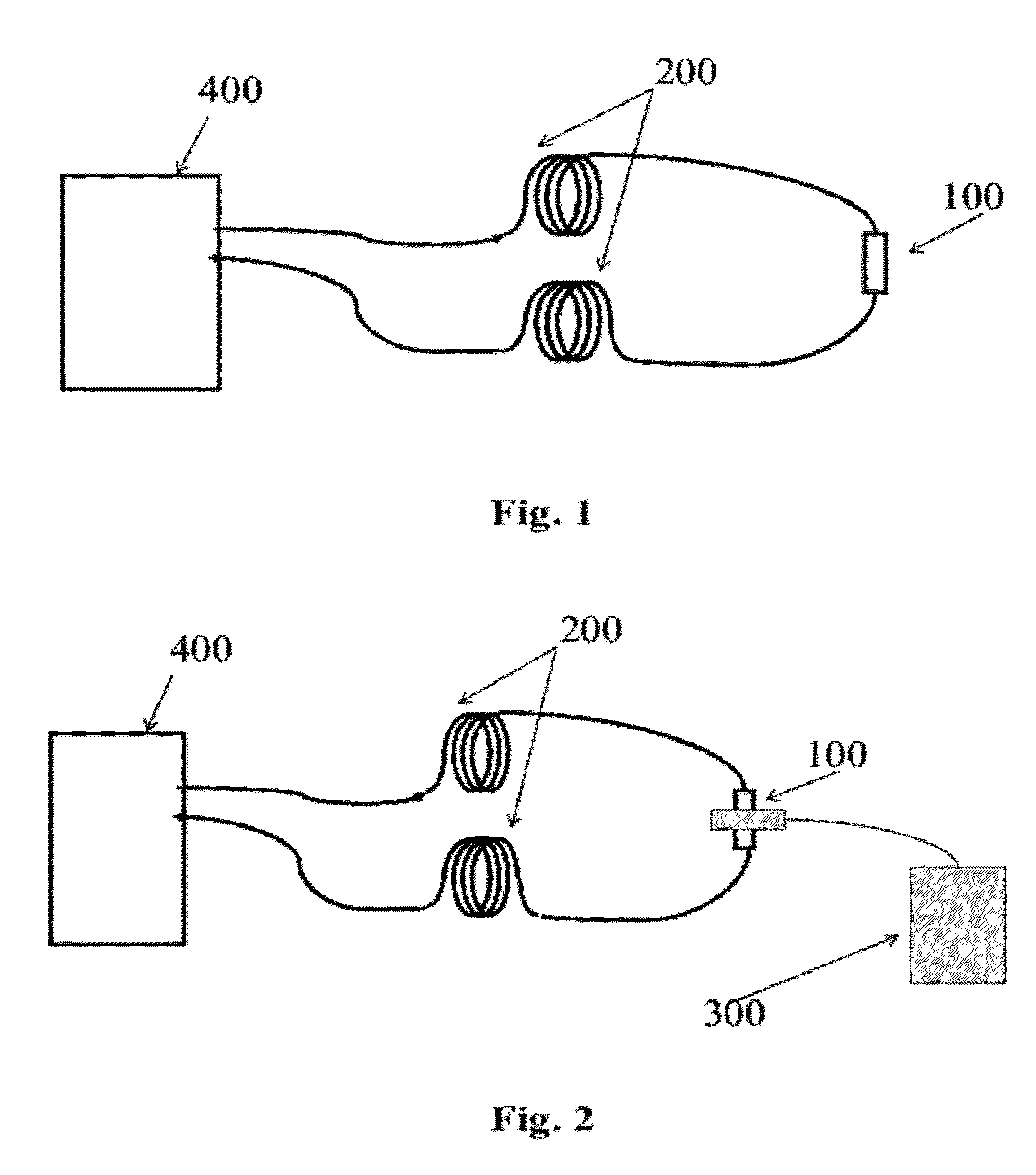
[0025]As shown in FIG. 2, the present embodiment provides a fiber magneto-optic detection system comprising: a magneto-optic probe 100, a fiber device 200, a reference device 300 and a power supply and signal processing module 400, in which the magneto-optic probe 100 and the reference device 300 are placed around a measurement point which may be located with a high electric potential, the power supply and signal processing module 400 is placed with a safe zero or low electric potential, and an insulated conductive fiber device 200 connects them.

[0026]The reference device 300 is used for generating a reference magnetic field at the measurement point with known amplitude and shape.

[0027]The magneto-optic probe 100 is used for detecting magnetic field signal at the measurement point and converting the magnetic field signal into optical signal which is carried by the received laser light for transmission and in which the magnetic field signal is superposition of the reference magnetic ...

embodiment 2

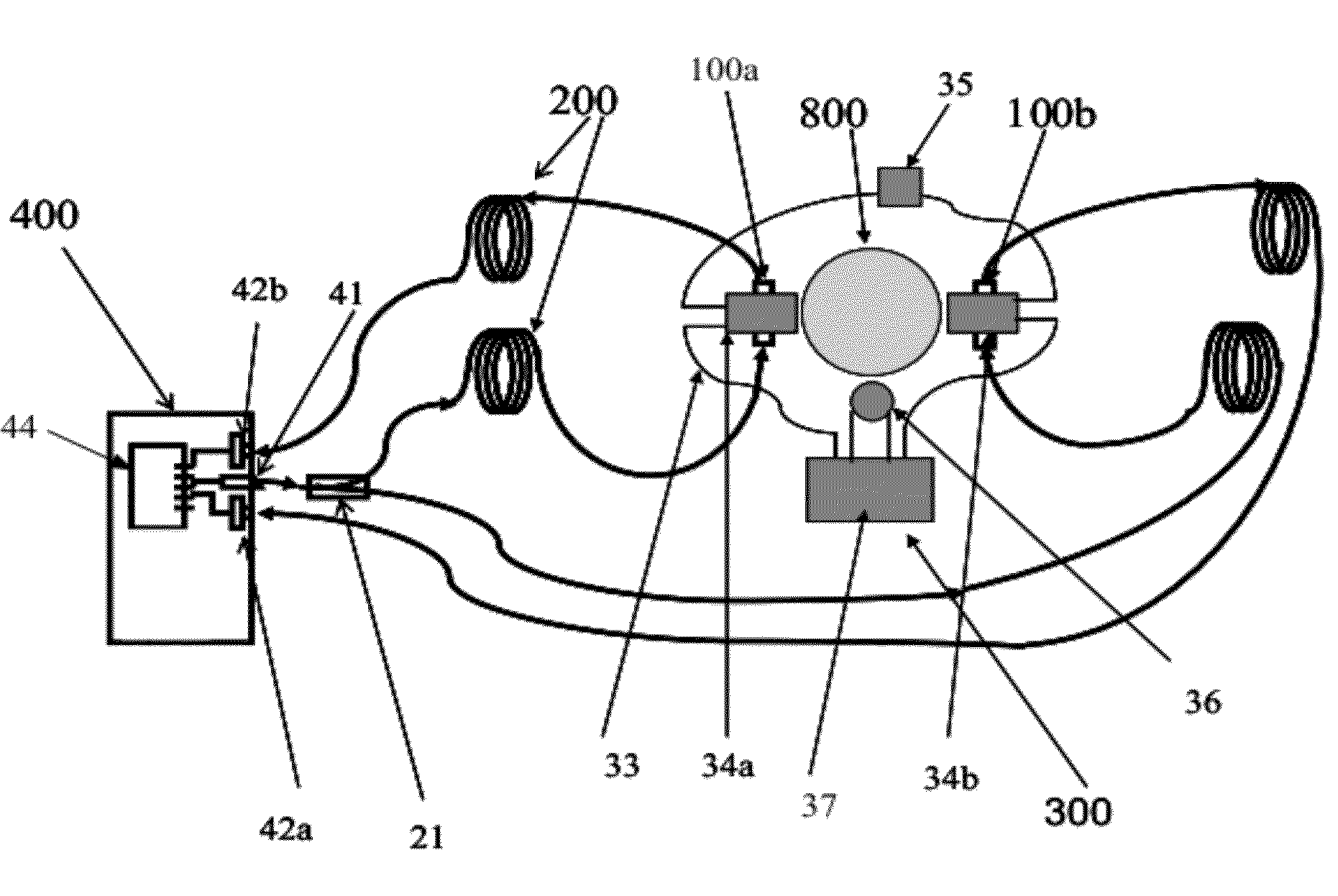
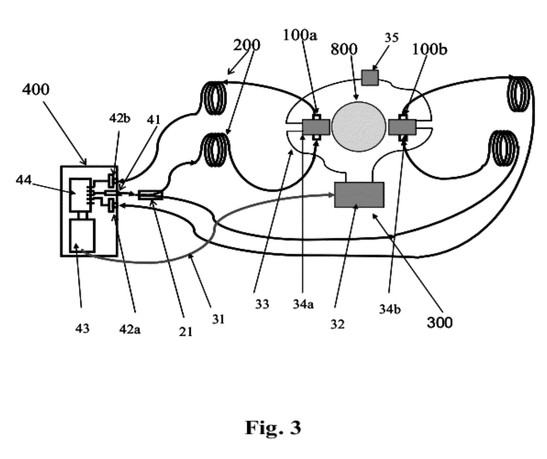
[0031]As shown in FIG. 3, the present embodiment provides a fiber magneto-optic detection system which is similar with that of Embodiment 1 and which comprises a magneto-optic probe 100, a fiber device 200, a reference device 300 and a power supply and signal processing module 400. The magneto-optic probe 100 and the reference device 300 are placed around the measurement point with a high electric potential, the power supply and signal processing module 400 is placed at a position with a safe zero or low electric potential, and the insulated conductive fiber device 200 connects them.

[0032]In the system, there are two magneto-optic probe 100, i.e., a first magneto-optic probe 100a and a second magneto-optic probe 100b, which are symmetrically placed at the two sides of the measurement point respectively.

[0033]Accordingly, the power supply and signal processing module 400 includes:

[0034]a detection laser device 41 for providing laser light signal to the first magneto-optic probe 100a ...

embodiment 3

[0049]As shown in FIG. 4, the present embodiment provides a fiber magneto-optic detection system which is similar with that of Embodiment 1 and which comprises a magneto-optic probe 100, a fiber device 200, a reference device 300 and a power supply and signal processing module 400. The magneto-optic probe 100 and the reference device 300 are placed around the measurement point with a high electric potential, the power supply and signal processing module 400 is placed at a position with a safe zero or low electric potential and the insulated conductive fiber device 200 connects them.

[0050]Different from that in Embodiment 2, the reference device 300 of the present embodiment includes: a power collection module 36, a reference signal modulating module 37 used to replace the photoelectrical module 32 in FIG. 3, conductive wires 33, a first coil 34a and a second coil 34b, and a temperature compensation device 35. The power collection module 36 collects power with a given magnitude (for ...


PUM


Abstract

A system and method for fiber magneto-optic detection are provided, which belongs to the optical application field. The system comprises: a reference device (300) for generating a reference magnetic field signal with known amplitude and shape at a measurement point; a magneto-optic probe (100) for detecting a magnetic field signal of the measuring point, converting the magnetic field signal into an optical signal, and transmitting to a power supply and signal processing module (400) the optical signal sent by the magneto-optic probe; the power supply and signal processing module (400) for transmitting laser light, and converting the optical signal into an electrical signal after receiving it, and demodulating and analyzing the electric signal to acquire the magnetic field information and / or the current information of the measuring point. The reference device (300) is provided in the system, and the measured signals can be corrected by the reference magnetic field signal generated by the reference device (300) to remove the influences environment factors cause on the measurement. Thus accurate measurement data are acquired and the measurement accuracy of the system is improved.

Description

FIELD OF THE INVENTION[0001]The invention relates to the field of optical application, particularly to a fiber magneto-optic detection system and method thereof.BACKGROUND[0002]Magneto-optic effects such as Faraday Effect are popularly used in measurement of the electrical current or magnetic field. Magneto-optic glass, magneto-optic crystal or fiber etc. is usually used for achieving Faraday Effect.[0003]As shown in FIG. 1, a fiber magneto-optic detection system in the prior art is shown comprising a power supply and signal processing module 400, a magneto-optic probe 100 and a conductive fiber device 200. The power supply and signal processing module 400 emits laser light which is transmitted to the magneto-optic probe 100 through the fiber device 200. The magneto-optic probe is designed to sense the magnetic field of the environment in which the magneto-optic probe 100 is located, based on a certain optical principle such as Faraday Effect, and convert the magnetic field signal i...

Claims


Application Information

Patent Timeline
Patent Type & Authority Patents(United States)
IPC IPC(8): G01R33/02G01R31/00G01R15/24G01R33/00G01R33/032
CPCG01R33/032G01R33/0041G01R15/246
Inventor YUAN, HAIJUN
Owner SIEYUAN ELECTRIC CO LTD
Why Eureka
Try Eureka