
Wavelet denoising for time-domain network analysis

a network analysis and wavelet denoising technology, applied in the field of network analysis instruments, can solve problems such as considerable noise, and achieve the effect of high dynamic rang

Active Publication Date: 2014-09-23
TELEDYNE LECROY
View PDF9 Cites 2 Cited by
  • Summary
  • Abstract
  • Description
  • Claims
  • Application Information

AI Technical Summary

Benefits of technology

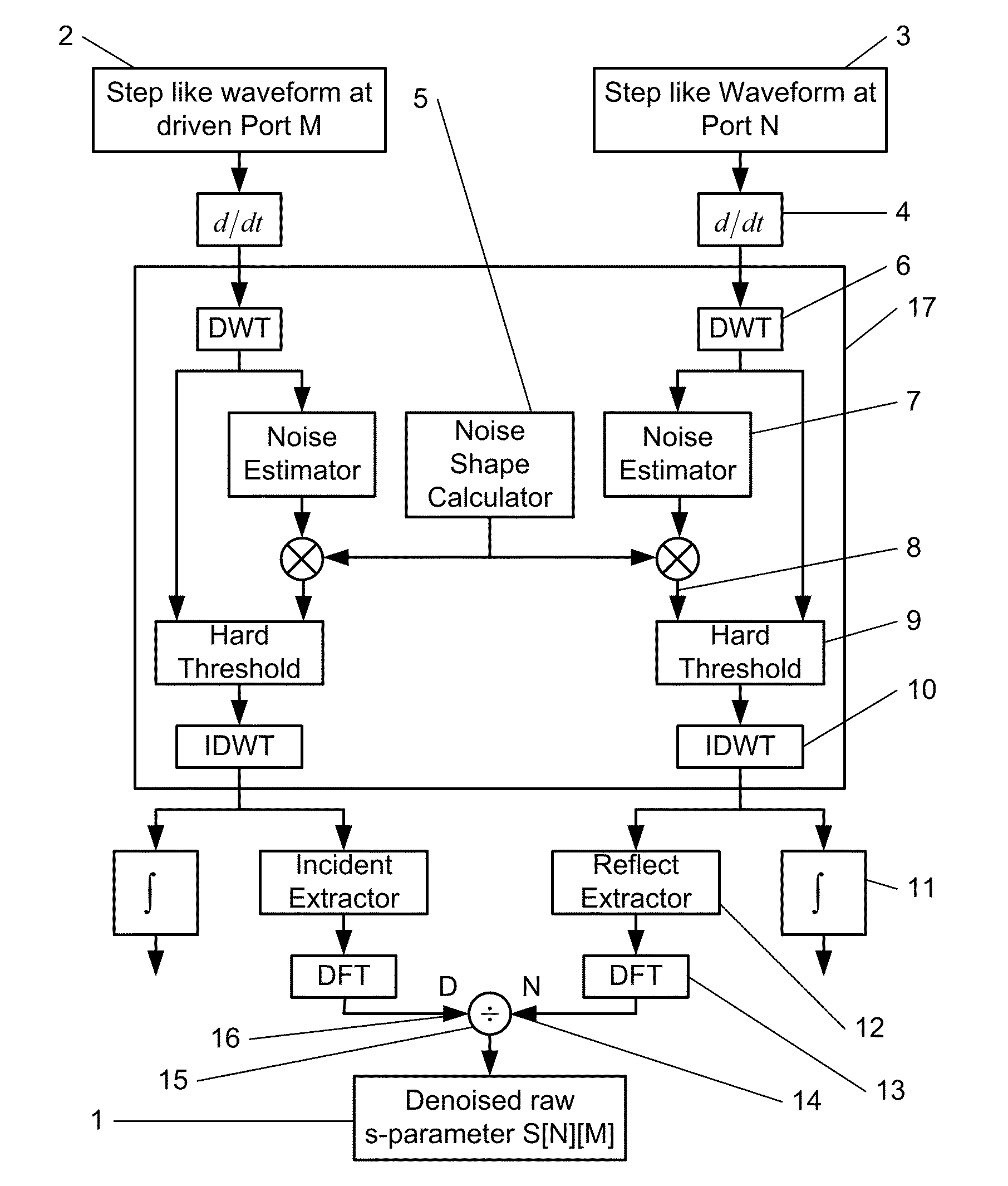
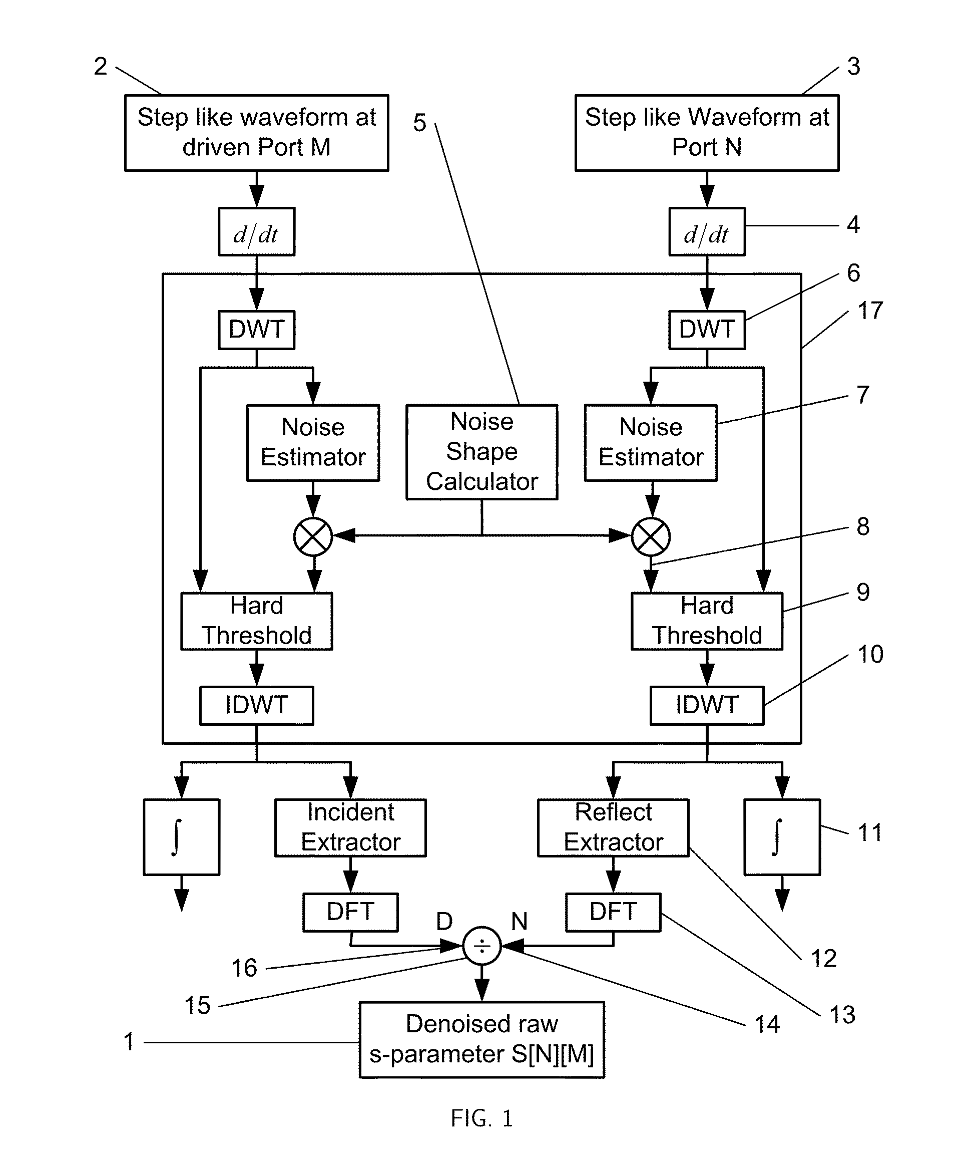
The present invention provides methods for network analysis that offer high dynamic range. The invention utilizes a denoising block that transforms the original waveform to a denoised difference waveform with significant noise removed while retaining key waveform features that measure crosstalk. The noise is homogeneous in the region of the key signal features and spread over the entire frequency spectrum of interest. This results in a denoised waveform with improved signal-to-noise ratio and dynamic range.

Problems solved by technology

It is illustrative because the device is electrically long requiring longer time domain waveforms, is lossy, and, as will be explained subsequently, involves considerable noise.

Method used


Image

  • Wavelet denoising for time-domain network analysis
  • Wavelet denoising for time-domain network analysis
  • Wavelet denoising for time-domain network analysis

Examples


Embodiment Construction

[0049]A detailed description of the invention will now be provided, making reference to the following drawings in which like reference numbers designate similar structure or steps.

[0050]In accordance with the invention, it can be shown that an expression for dynamic range in a time domain network analysis instrument is expressed as:

[0051]SNRn=10·Log(A2·Fseq·avgTa·f2)-NdBm-C⁡(f)+P⁡(f)-6(1)

[0052]In equation (1), A is the amplitude of an incident step waveform in Volts, Fseq is the equivalent time sample rate in samples per second, avg is the number of averages taken, Ta is the length of the waveform in seconds, f is the frequency in Hertz, NdBm is the power of the assumed white noise in decibels relative to 1 mW delivered to a 50 Ohm load (dBm), C(f) is the attenuation of the cabling in dB as a function of frequency and P(f) is the response of the puller in dB as a function of frequency and is computed as the frequency content in the derivative of the step waveform. The dynamic range ...


PUM


Abstract

A method and apparatus are provided for the removal of significant broad-band noise from waveforms acquired for time domain network analysis. The method may include the steps of providing the noisy waveform as an input waveform, determining a frequency domain noise shape associated with the input waveform, calculating a wavelet domain noise shape from the frequency domain noise shape, calculating a discrete wavelet transform of the input waveform to form a wavelet domain waveform, and estimating the noise statistics from the wavelet domain waveform. A threshold may be calculated from the estimated noise statistics and the wavelet domain noise shape, and the threshold may be applied to the wavelet domain waveform to form a denoised wavelet domain waveform. Finally, an inverse discrete wavelet transform of the denoised wavelet domain waveform may be calculated to form a denoised waveform.

Description

CROSS REFERENCE TO RELATED APPLICATIONS[0001]This application claims the benefit of U.S. Provisional Patent Application 61 / 300,149, filed Feb. 1, 2010 titled “Wavelet Denoising” to Pupalaikis et al.; U.S. Provisional Patent Application 61 / 300,160, filed Feb. 1, 2010 titled “Wavelet Denoising” to Pupalaikis et al.; U.S. Provisional Patent Application 61 / 300,230, filed Feb. 1, 2010 titled “Time Domain Reflectometry Step to S-Parameter Conversion” to Pupalaikis et al.; and U.S. Provisional Patent Application 61 / 355,182, filed Jun. 16, 2010 titled “Wavelet Denoising for Time-Domain Network Analysis” to Pupalaikis et al., the contents of each of these applications being incorporated herein by reference.FIELD OF THE INVENTION[0002]The present invention relates to network analysis instruments in general and specifically to network analysis instruments that measure scattering parameters (s-parameters) and more specifically to s-parameter measurement instruments using time domain methods and...

Claims


Application Information

Patent Timeline
Patent Type & Authority Patents(United States)
IPC IPC(8): G01R29/26G06F17/18G16Z99/00
CPCG01R29/26G06F19/00G06F17/18G16Z99/00
Inventor PUPALAIKIS, PETER J.SUREKA, ANIRUDHDOSHI, KAVIYESH
Owner TELEDYNE LECROY
Learn More