Torque sensor

a technology of torque sensor and torque sensor, which is applied in the direction of electrical steering, instruments, transportation and packaging, etc., can solve the problem of increasing the calculation load of the ecu for carrying out the process of determining the fault of the magnetic sensor, and achieve the effect of reducing space and weight and simple structur

Active Publication Date: 2014-09-30
DENSO CORP
View PDF9 Cites 10 Cited by
  • Summary
  • Abstract
  • Description
  • Claims
  • Application Information

AI Technical Summary

Benefits of technology

[0009]The present disclosure is made in view of the above problem. It is an object of the present disclosure to provide a magnetic detecting device, according to which a circuit size and a number of wire harnesses can be reduced and it is possible with a simple structure to determine failure of a magnetic sensor.
[0013]According to the above feature, it is possible to determine by the comparator, inside of the magnetic detecting device, whether the magnetic sensor is out of order. The magnetic detecting device outputs the authorized detection value when the magnetic sensor is operating in a normal condition, while the magnetic detecting device outputs the abnormal determination signal when the magnetic sensor is out of order. Therefore, it is not necessary for the ECU connected to the magnetic detecting device to carry out a process for the determination of a faulty magnetic sensor. The calculation load for the ECU is thereby reduced.
[0015]In the present disclosure, two wire harnesses are provided between two magnetic sensors and the ECU. It is, therefore, possible to reduce the space and weight for the wire harnesses, compared with the prior art torque sensor which has three magnetic sensors.
[0018]In an electric power steering system for a vehicle, the torque sensor detects a steering torque applied to a steering shaft. There is a demand for the electric power steering system to reduce its space and weight. The present disclosure has an advantage that it is possible to determine with a simple structure whether the magnetic sensor is out of order. Therefore, the magnetic detecting device of the present disclosure can be effectively applied to the torque sensor.

Problems solved by technology

In addition, although the torque sensor of the above prior art has an advantage that it is possible to determine whether the magnetic sensor becomes out of order, it is a problem that calculation load of the ECU for carrying out a process of determining the faulty magnetic sensor is increased.

Method used


Image

  • Torque sensor
  • Torque sensor
  • Torque sensor

Examples


first embodiment

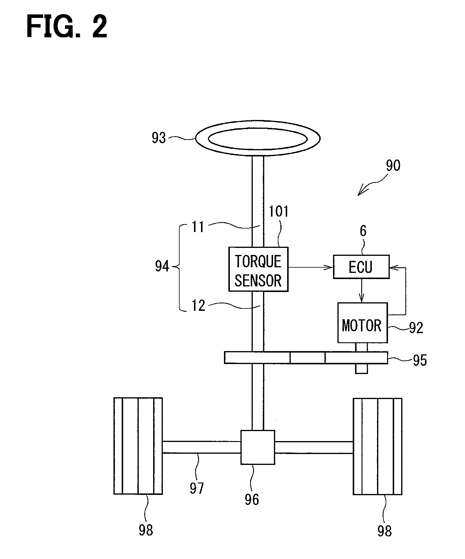
[0033]As shown in FIG. 2, a torque sensor 101 of a first embodiment of the present disclosure is applied to, for example, an electric power steering apparatus 90 for a vehicle for assisting a steering operation of a vehicle driver.

[0034]FIG. 2 shows a structure for a steering system having the electric power steering apparatus 90. The torque sensor 101 for detecting a steering torque is provided in a steering shaft 94 connected to a steering wheel 93. A pinion gear 96 is provided at a forward end of the steering shaft 94. The pinion gear 96 is engaged with a rack shaft 97. A pair of wheels 98 is rotatably connected to both ends of the rack shaft 97 via respective tie rods. A rotational movement of the steering shaft 94 is converted to a linear movement of the rack shaft 97 by the pinion gear 96, so that the steering operation of the wheels 98 is carried out.

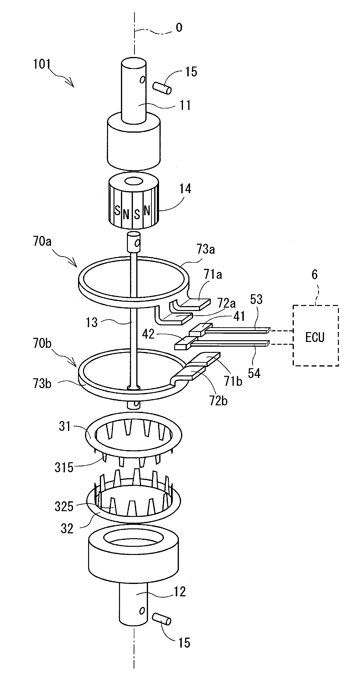
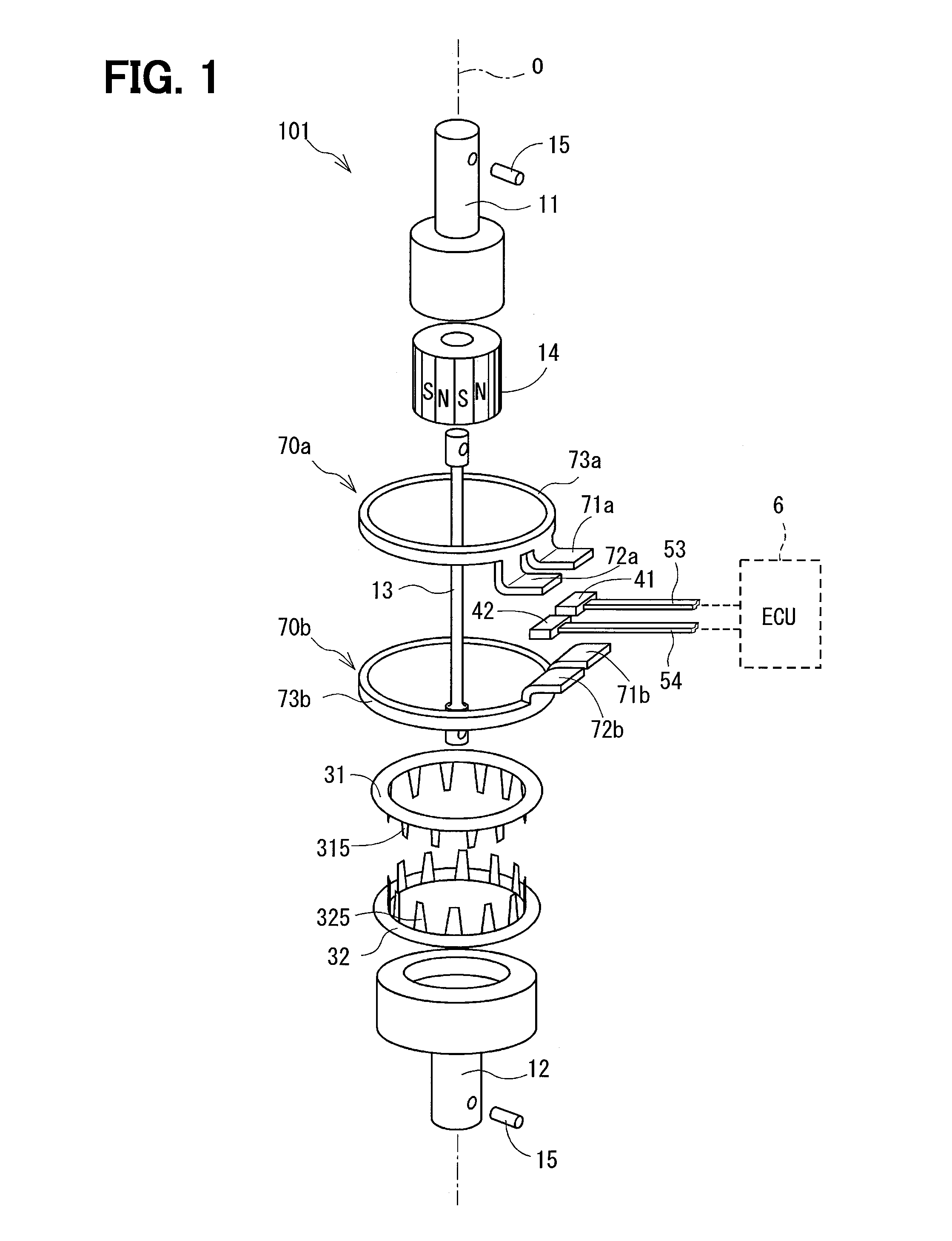
[0035]The torque sensor 101 is provided between an input shaft 11 and an output shaft 12, each of which constitutes the steerin...

second embodiment

[0081]According to a torque sensor 102 of a second embodiment, only one magnetic sensor 41, which is substantially the same to that of the first embodiment, is provided. In a case that it is not necessary to continue the control by the ECU when the magnetic sensor 41 becomes out of order, two magnetic sensors are not always necessary. Since the ECU 6 does not require the calculation unit 61 in the second embodiment, the calculation load for the ECU 6 can be further reduced.

third embodiment

[0082]A torque sensor 103 of a third embodiment shown in FIG. 8 differs from that of the first embodiment in a structure for IC packages accommodating the magnetic detecting elements.

[0083]According to the third embodiment, each of magnetic detecting elements 431 and 442 (for the detection signal and for the reference signal) of a first magnetic sensor 410 is accommodated in respective IC packages 43 and 44. In a similar manner, each of magnetic detecting elements 451 and 462 (for the detection signal and for the reference signal) of a second magnetic sensor 420 is accommodated in respective IC packages 45 and 46. Each of the comparators 51 and 52 is provided in the respective magnetic sensors 41 and 42 independently from the IC packages 43, 44 and 45, 46.

[0084]Wire harnesses between the respective magnetic sensors 410 and 420 and the ECU 6 are the same to those of the first embodiment. However, in FIG. 8, only the signal lines 53s and 54s are indicated.

[0085]As shown in FIG. 8, the...


PUM

PropertyMeasurementUnit
magnetic fieldaaaaaaaaaa
magnetic-fieldaaaaaaaaaa
densityaaaaaaaaaa

Abstract

A torque sensor has a magnetic sensor, which is composed of a first magnetic detecting element, a second magnetic detecting element and a comparator. The first magnetic detecting element outputs an output signal of a provisional detection value, while the second magnetic detecting element outputs an output signal of a reference value. The comparator compares the provisional detection value and the reference value and outputs the provisional detection value as an authorized detection value, when a difference value between the provisional detection value and the reference value is smaller than a predetermined threshold value.

Description

CROSS REFERENCE TO RELATED APPLICATION[0001]This application is based on Japanese Patent Applications No. 2012-251304 filed on Nov. 15, 2012, and No. 2013-154671 filed on Jul. 25, 2013, the disclosures of which are incorporated herein by reference.FIELD OF TECHNOLOGY[0002]The present disclosure relates to a magnetic detecting device having a magnetic-field generating member and a magnetic sensor, and in particular, to a torque sensor having the above magnetic detecting device.BACKGROUND[0003]A magnetic detecting device is known in the art. The magnetic detecting device has a magnetic-field generating means and a magnetic sensor. The magnetic sensor detects intensity of magnetic field generated by the magnetic-field generating means, which is movably provided relative to the magnetic sensor. The magnetic sensor detects a relative displacement of a detection subject, which is connected to either the magnetic-field generating means or the magnetic sensor.[0004]This kind of magnetic det...

Claims


Application Information

Patent Timeline
Patent Type & Authority Patents(United States)
IPC IPC(8): G01L3/02B62D6/10G01L3/10
CPCG01L3/101B62D6/10G01L3/104G01L3/10B62D5/04
Inventor TAKAHASHI, YOSHIKIFUKAYA, SHIGETOSHIKABUNE, HIDEKI
Owner DENSO CORP
Why Eureka
Try Eureka