Reversible lifting lug

a technology of lifting lugs and lugs, which is applied in the field of reversible lifting lugs, can solve the problems of material hanging up, material damage, material life reducing, etc., and achieve the effect of inhibiting abrasion

Inactive Publication Date: 2014-10-07
ALLOY STEEL AUSTRALIA INT
View PDF9 Cites 3 Cited by
  • Summary
  • Abstract
  • Description
  • Claims
  • Application Information

AI Technical Summary

Benefits of technology

[0015]The plug substantially fills the hole when the lug is in the second position to minimise any irregularities formed in the upper load bearing surface of the wear plate over which the bulk material slides. Irregularities in the upper surface of the wear plate such as ridges and groove can increase the abrasion of the wear plate. Furthermore the irregularities can increase turbulence in the material being handled, which leads to increased abrasion both of the wear plate and within the actual material. This increase in localised abrasion can reduce the lifespan of the wear plate and increase degradation of the material being handled.
[0016]In this way the coupling means of the lug can be positioned so that it extends outwardly from the upper surface of the wear plate when the wear plate is being installed or removed from a hopper or chute. Once the wear plate has been installed the lug can be detached, reversed and reattached such that the plug substantially fills the hole to provide a smooth upper surface that inhibits abrasion.
[0028]In this way the lug of the present invention provides a means for lifting the wear plate during installation or replacement, and a means for filling a hole in the wear plate, used for the passage of the coupling means, to thereby inhibit abrasion while the wear plate is installed within the hopper or chute.

Problems solved by technology

Irregularities in the upper surface of the plate such as bolt heads extending out therefrom or hollows, leads to an increase in localised turbulence, which can result in damage to the wear plate thereby reducing its life span, or damage to the material being handled.
Since the underside of the plates is attached to the hopper or chute the coupling means must be positioned adjacent the outer or upper surface of the plate, which can result in irregularities in the upper surface.
However this results in holes or depressions that during use can cause hangup of material or generally increase localised wear of the plate.
Likewise permanently fixed lugs result in irregularities in the outer surface that can result in increased abrasion or damage to the material being handled.

Method used


Image

  • Reversible lifting lug
  • Reversible lifting lug
  • Reversible lifting lug

Examples


Embodiment Construction

[0044]There are numerous specific details set forth in the following description. However, from the disclosure, it will be apparent to those skilled in the art that modifications and / or substitutions may be made without departing from the scope and spirit of the invention. In some circumstance specific details may have been omitted or enlarged so as not to obscure the invention. Similar reference characters indicate corresponding parts throughout the drawings.

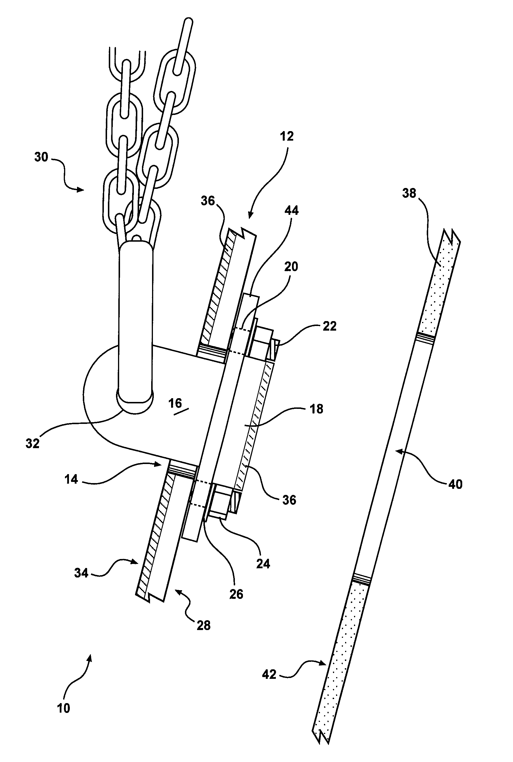
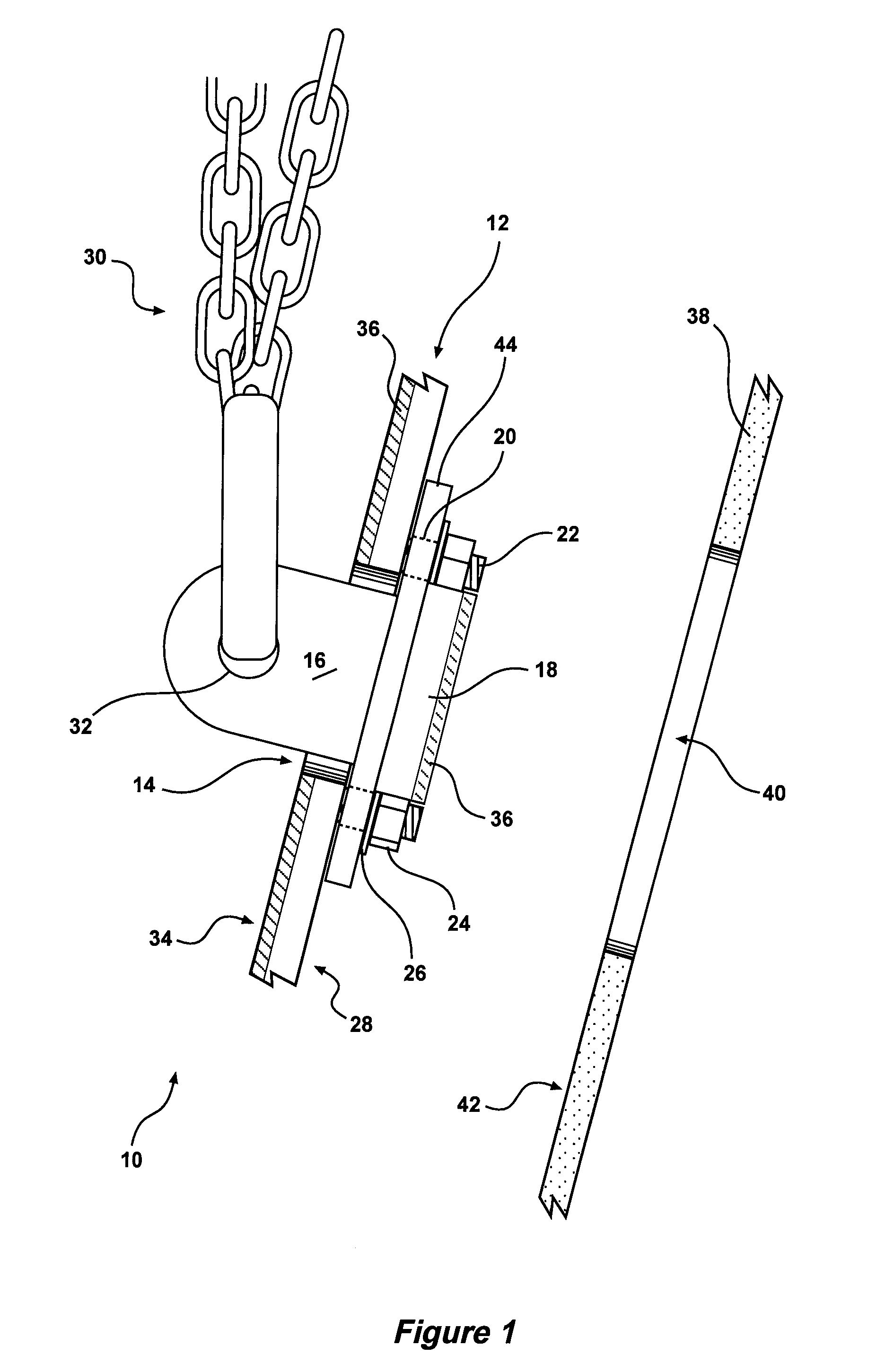
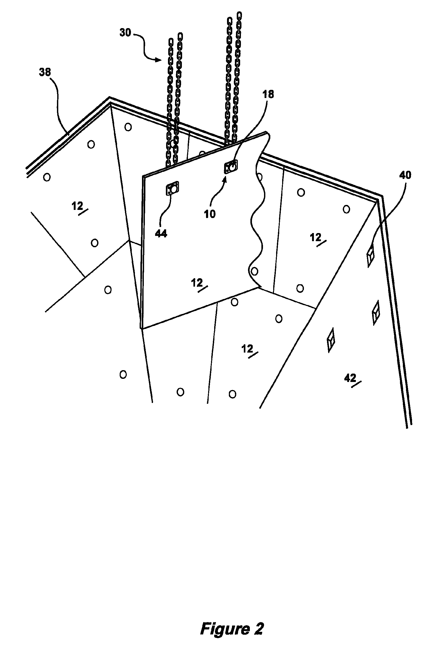
[0045]Turning to the figures for a detailed explanation of the invention, there is illustrated a lug 10 that can be reversible attached to a wear plate 12 demonstrating by way of an example, an arrangement in which the principles of the present invention may be employed. As illustrated in FIG. 1 the reversible lug 10 can be reversibly connected to the wear plate 12. The plate 12 includes a hole 14 that extends therethrough, and the lug 10 includes a coupling means 16 and plug 18 dimensioned to, in one orientation, substantially...


PUM

PropertyMeasurementUnit
circumferenceaaaaaaaaaa
wear resistantaaaaaaaaaa
hardaaaaaaaaaa

Abstract

A lug reversibly connectable to a wear plate having a hole extending therethrough. The lug includes a coupling means and a plug. The plug comprises an upper surface. In a first position the lug is connectable to an underside of the wear plate such that the coupling means extends through said hole and outward from an upper surface of the wear plate an in this position can be engaged by a hoist. In a second position the lug is connectable to the underside of said wear plate such that the plug fills said hole whereby the upper surface of the plug is aligned with the upper surface of the wear plate to thereby present an even wear surface.

Description

FIELD OF THE INVENTION[0001]The present invention relates generally to lifting lugs for wear liners and in one aspect relates to a lug that can be reversibly mounted to a wear plate.BACKGROUND OF THE INVENTION[0002]Wear plates may be used for numerous applications to protect an underlying surface or to protect a material being handled. Wear plate may be constructed from a uniform material, such as a chromium or tungsten alloy, or the plate may be asymmetric and comprise a layer of alloy, rubber, ceramic or polyurethane that overlays a steel plate.[0003]The wear plate may include an upper surface that provides a generally continuous and smooth sliding surface to enhance the sliding of material thereover and reduce hangup of the material.[0004]The wear plate may comprise a layer of hard surfaced alloy over a mild steel base. It is the hard faced surface of the wear plate which contacts the material being handled and over which the material slides during loading or unloading. Wear resi...

Claims


Application Information

Patent Timeline
Patent Type & Authority Patents(United States)
IPC IPC(8): B66F19/00B66C1/10
CPCB66C1/10Y10T403/70Y10T29/49817
Inventor KOSTECKI, GENE
Owner ALLOY STEEL AUSTRALIA INT
Why Eureka
Try Eureka