Methods and apparatus for treating water and wastewater employing a cloth disk filter

a cloth disk and filter technology, applied in the direction of filtration separation, sedimentation settling tanks, separation processes, etc., can solve the problems of only being able to clean a single cloth surface, contaminating the filtered water, and common approaches, so as to reduce or overcome deficiencies and increase backwashing efficiency

Active Publication Date: 2014-10-07
ALFA LAVAL CORP AB
View PDF64 Cites 26 Cited by
  • Summary
  • Abstract
  • Description
  • Claims
  • Application Information

AI Technical Summary

Benefits of technology

[0009]Apparatus and methods of the present disclosure reduce or overcome deficiencies of prior art backwash shoes, and cloth disk filters employing them, by providing completely redesigned backwash headers. By including such backwash headers in cloth disk filters, increased backwash efficiencies may be achieved, as further explained herein.
[0015]wherein the structure is configured to allow relatively clean fluid to pass through the filter material in a reverse direction upon application of a suction pressure in the internal cavity, and allow the relatively clean fluid and solids previously adhered to the fibers to enter the chamber, then the slot and internal cavity while substantially preventing other relatively less clean fluids and solids from entering the chamber, slot and internal cavity.
[0019]a hood structure attached to a portion of the exterior surface of the body around and extending away from the suction slot to form a chamber defined by the structure and a portion of the exterior surface near the slot, the chamber comprising first and second sub-chambers on opposites sides of the slot, wherein the sub-chambers have sufficient volume to allow gradual straightening and relaxing of fibers of a filter material being cleaned by the backwash header, wherein the hood structure is configured to allow relatively clean fluid to pass through the filter material in a reverse direction upon application of a suction pressure in the internal cavity, and allow the relatively clean fluid and solids previously adhered to the fibers to enter the chamber, then the slot and internal cavity while substantially preventing other relatively less clean fluids and solids from entering the chamber, slot and cavity.
[0029]a hood structure attached to a portion of the exterior surface of the body around and extending away from the suction slot to form a chamber defined by the structure and a portion of the exterior surface near the slot, the chamber comprising first and second sub-chambers on opposites sides of the slot, wherein the sub-chambers have sufficient volume to allow gradual straightening and relaxing of fibers of a filter material being cleaned by the backwash header, wherein the hood structure is configured to allow relatively clean fluid to pass through the filter material in a reverse direction upon application of a suction pressure in the internal cavity, and allow the relatively clean fluid and solids previously adhered to the fibers to enter the chamber, then the slot and internal cavity while substantially preventing other relatively less clean fluids and solids from entering the chamber, slot and cavity.
[0036]wherein the structure allows relatively clean fluid to pass through the cloth filter media in a reverse direction upon application of suction in the internal cavity supplied by a backwash pump fluidly connected to the backwash header, and allow a relatively clean fluid plus solids previously adhered to the fibers to enter the chamber, then the slot and then the internal cavity, while substantially preventing other relatively less clean fluids and solids from entering the chamber, slot and internal cavity.

Problems solved by technology

The limitations of these common approaches are the following.
The shoes are only capable of cleaning a single cloth surface.
The leading edge of the flat underside may compress, squeeze, and dislodge captured solids out of the reach of the suction of the backwash system; and even worse may force solids through the cloth to the filtered water side, thereby contaminating the filtered water.
The flat underside may not provide for a volume of high turbulence that would enhance the cleaning / scouring effect by filtered water, and may not prevent “short-circuiting” of unfiltered secondary effluent into the shoe.
Backwash shoes that raise the shoe off the cloth surface inherently weaken the impact of the suction cleaning Non-metallic shoes, while perhaps less expensive to fabricate compared with stainless steel shoes, represent a potential wear item over years of service.
The sharp edges of these shoes naturally tend to abrade, fray, and otherwise wear the cloth surface.
In those applications, usually the cloth filter disk shows very short filter run and frequent backwash.

Method used


Image

  • Methods and apparatus for treating water and wastewater employing a cloth disk filter
  • Methods and apparatus for treating water and wastewater employing a cloth disk filter
  • Methods and apparatus for treating water and wastewater employing a cloth disk filter

Examples


embodiment 100

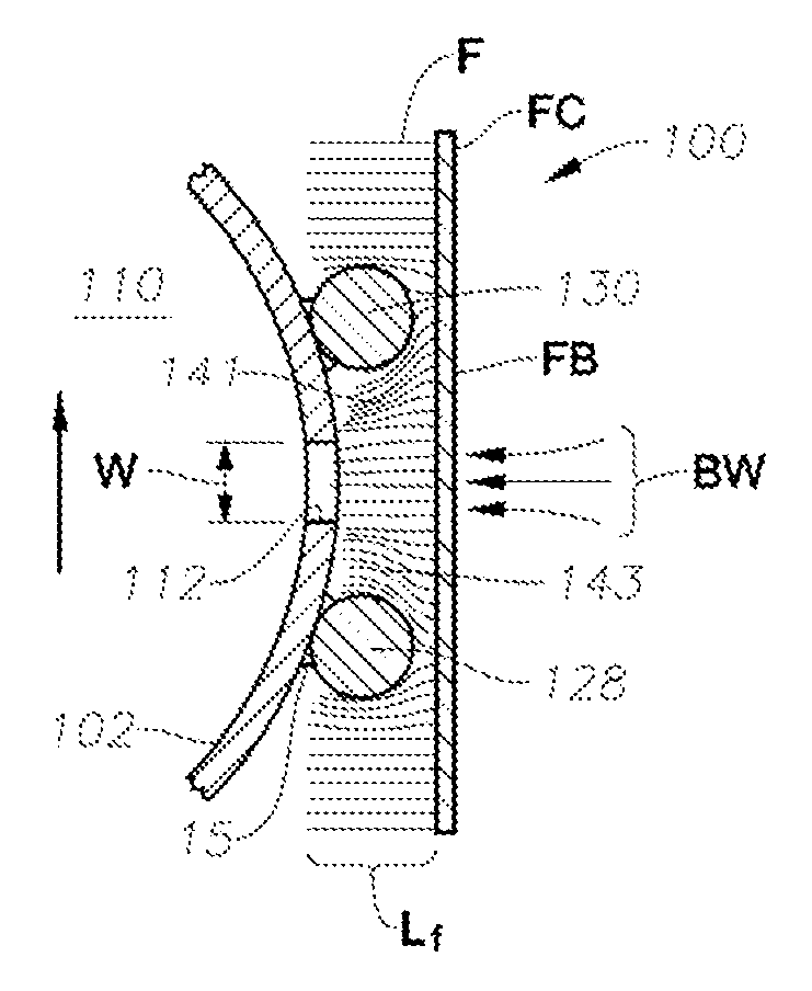
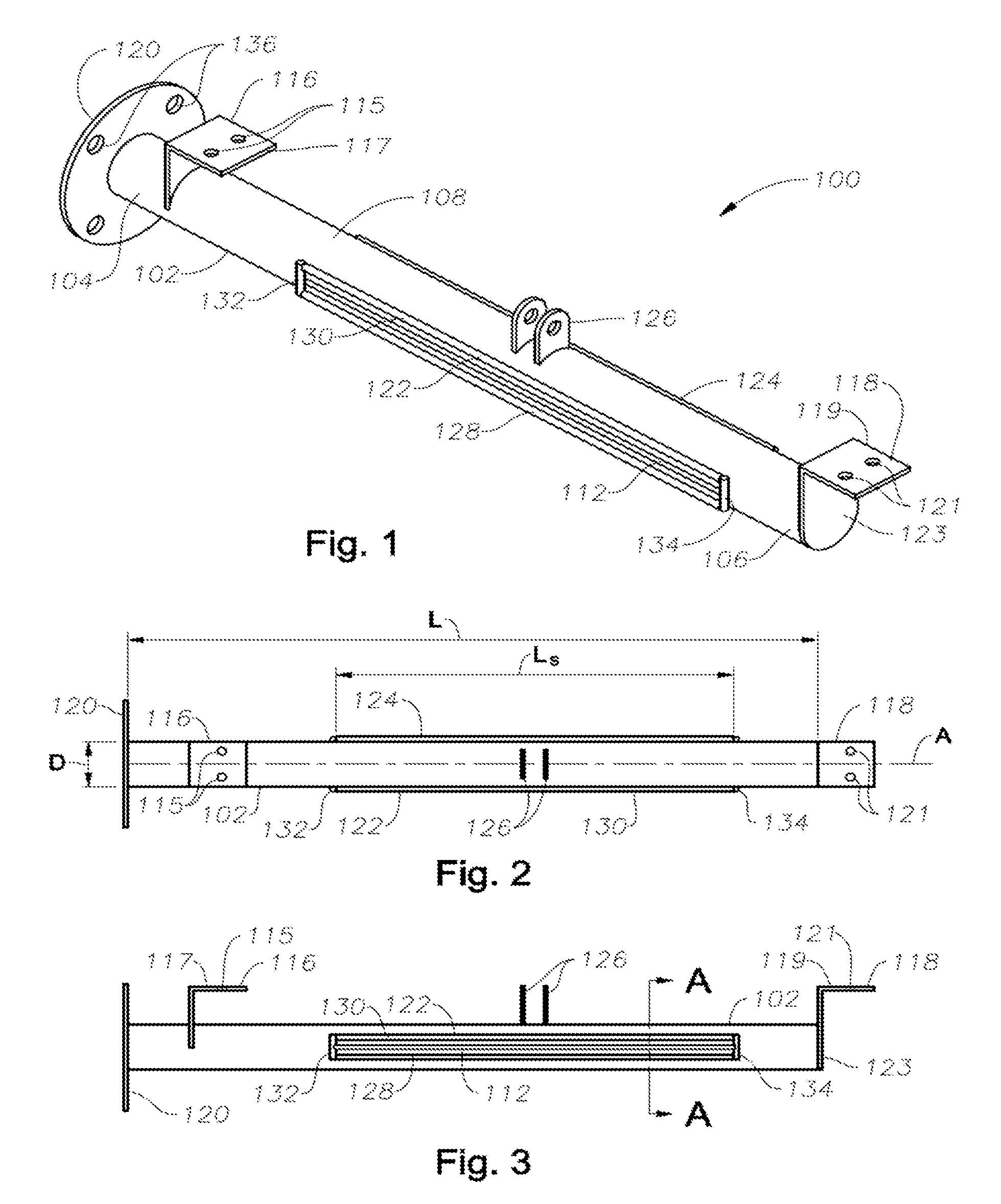
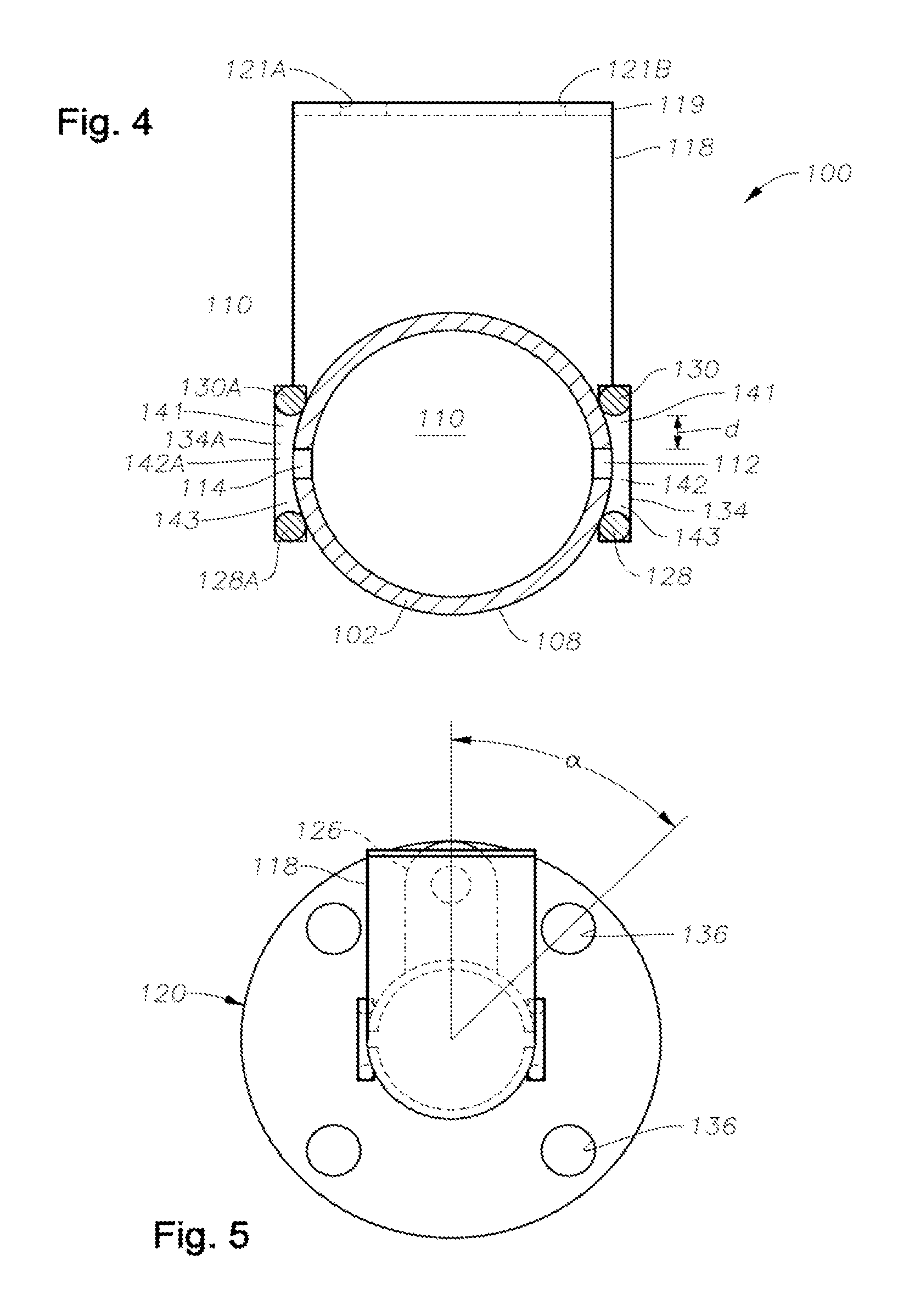
[0065]Referring now to the drawing figures, FIG. 1 is a schematic perspective view of one embodiment 100 of a backwash header in accordance with the present disclosure, having a tubular body 102, a first end 104, a second end 106, and an exterior surface 108. Tubular body 102 defines at least one cavity 110, in this embodiment a single cavity 110, more clearly visible in FIG. 4. Although embodiment 100 comprises a tubular body that is substantially cylindrical (circular) in cross-section, “tubular” is not meant to be limited to cylindrical bodies. Tubular bodies having oval or polygonal (for example, rectangular and triangular) bodies may be envisioned and are considered within the present disclosure. Tubular body 102 may be steel, such as 304 or 316 stainless steel, titanium, aluminum, or other metal or metal alloy. In certain embodiments tubular body may be polymeric, such as a thermoplastic polymer, thermoplastic elastomer, or thermosetting polymer, or fiberglass reinforced plast...

embodiment 500

[0077]Another optional feature is the provision of a sludge concentration zone 157 between a pair or plurality of plates 154, 156 extending upward from the floor of vessel 2 at an angle from horizontal. Sludge concentration zone 157 may be described as a quiescent thickening zone. It need not be located as illustrated in the middle of vessel 2, this being only one possible embodiment. Embodiment 500 also illustrates an optional conduit 82 provided for withdrawing concentrated sludge from sludge concentration zone 157 when desired, for example through a valve 83. Concentrated sludge is typically routed to a belt filter press or to storage prior to being processed in a belt filter press, or other type of dewatering press. The dewatered sludge may be burned, landfilled, or otherwise disposed by alternate acceptable means if it meets applicable quality standards. Cleaned effluent fluid flows out of the filter through one or more effluent conduits 28, which may be manifolded together.

[00...


PUM

PropertyMeasurementUnit
diameteraaaaaaaaaa
diameteraaaaaaaaaa
distanceaaaaaaaaaa

Abstract

A backwash header for a cloth filter disk includes a body having a length a diameter, first and second ends, a longitudinal axis, and an exterior surface, the body defining at least one internal cavity. The body includes at least one suction slot configured to allow fluids and solids to enter the internal cavity from outside of the exterior surface. A structure is attached to a portion of the exterior surface of the body around and extending away from the suction slot to form a chamber defined by the structure and a portion of the exterior surface near the suction slot. The structure is configured to allow fluids and solids to enter the chamber and then the suction slot and cavity from a material being cleaned. Cloth disk filters and methods of treating water and wastewater using the backwash headers and cloth disk filters.

Description

CROSS-REFERENCE TO RELATED APPLICATIONS[0001]This application may be related to assignee's U.S. non-provisional patent application Ser. No. 12 / 905,454, filed Oct. 15, 2010.BACKGROUND INFORMATION[0002]1. Technical Field[0003]The present disclosure relates in general to the field of water and wastewater treatment.[0004]2. Background Art[0005]A cloth disk filter typically comprises a tank or vessel, which may be concrete, metal, fiberglass-reinforced plastic (FRP) or other material. A source of screened, secondary effluent flows into the unit from an influent trough, and filtered effluent leaves the unit through an effluent trough. Influent may traverse an influent weir, a scum or hydraulic optimization baffle, then approaches one or more filter cassettes. In currently known systems, each filter cassette may have at least one dedicated backwash vacuum shoe assembly positioned on one side of filter cloth fluidly attached to the central rotatable backwash conduit. In some other known emb...

Claims


Application Information

Patent Timeline
Patent Type & Authority Patents(United States)
IPC IPC(8): B01D37/00B01D29/68B01D33/50
CPCB01D29/39B01D29/684B01D2201/082
Inventor XIA, YONGMINGDEVINE, JEFFREY S.DANNEMANN, CHARLES G.
Owner ALFA LAVAL CORP AB
Why Eureka
Try Eureka