Conformal array, luneburg lens antenna system

a technology of luneburg lens and array, applied in the field of antennas, can solve the problems of increasing the weight of the pointing or steering gimbal increasing the cost of pointing, increasing the cost of maintenance, etc., and increasing the cost of pointing time lag, increasing the cost of installation and maintenance,

Active Publication Date: 2014-10-07
UNITED STATES OF AMERICA THE AS REPRESENTED BY THE SEC OF THE ARMY
View PDF21 Cites 20 Cited by
  • Summary
  • Abstract
  • Description
  • Claims
  • Application Information

AI Technical Summary

Benefits of technology

[0009]In operation, the received radar beam is focused on a receiving subarray such that a focal point or blur spot of the Luneburg lens includes at least a portion of all the patch antennas in a given subarray with each patch antenna of a given subarray utilizing a corresponding transmit / receive module for transmitting and receiving purposes. In transmit mode, by controlling the excitation of the various subarrays in the patch antenna array, the processor controls the steering of the outputted sum radar beams by selectively activating subarrays over a given time period. In the receive mode, periodic scanning and sweeping of the subarrays of the patch antenna array, along with selective use of the electronic feed elements, allows for the simultaneous formation of sum and difference radiation patterns for monopulse tracking.
[0010]As a result of electronic steering, the present invention removes the need of mechanically steered hardware, such as gimbal mechanisms.

Problems solved by technology

An antenna pointing or steering gimbal adds weight, cost, pointing complexity, and inertial angle-tracking time.
The electronically beam-steered phased array antennas of the prior art are very complex, expensive-to-build, and expensive-to-maintain.
Thus, phased-arrays and gimbals lend themselves to concomitant complexities, which include increased costs, steering time lag and weight.

Method used


Image

  • Conformal array, luneburg lens antenna system
  • Conformal array, luneburg lens antenna system
  • Conformal array, luneburg lens antenna system

Examples


Embodiment Construction

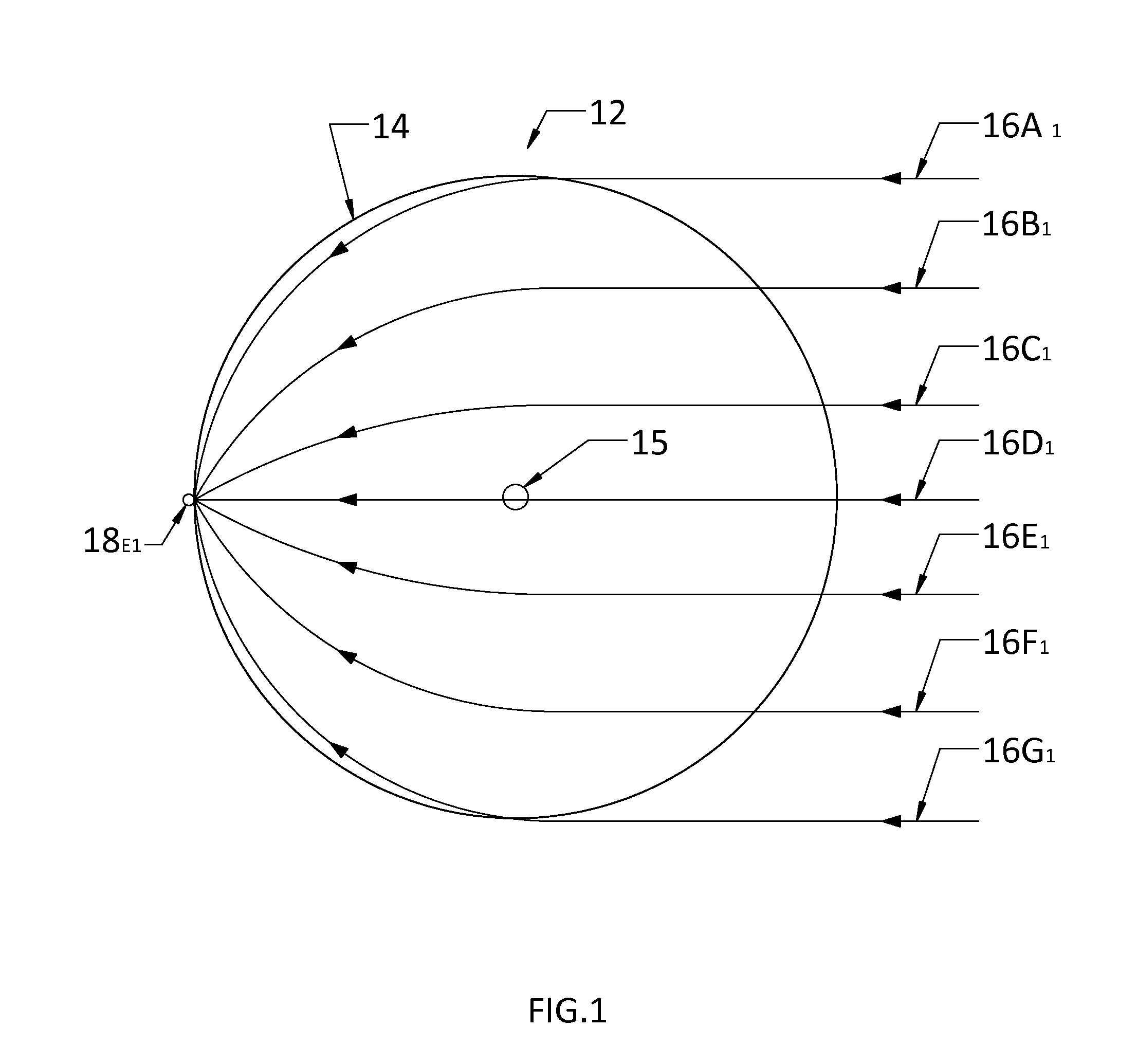
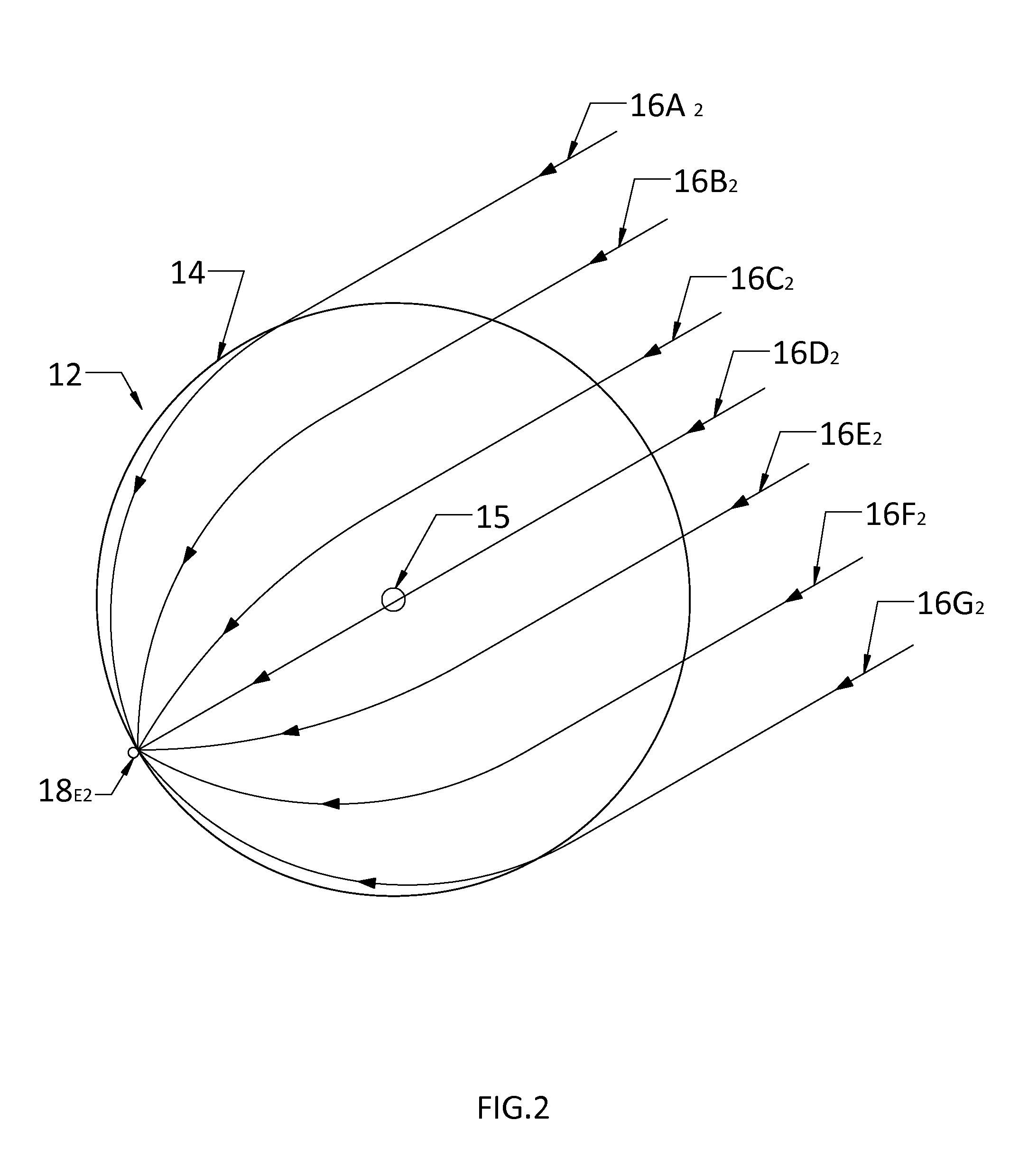
[0025]With respect to FIG. 1, a spherical radio frequency lens or Lunenburg lens 12, as utilized in the present invention, is composed of separate and concentric layers (not shown) each having a different dielectric constant according to the equation of Luneburg. The lens 12 has a surface 14 and a center region 15. As those in the art appreciate, an ideal Luneburg lens is a sphere having an index of refraction of 1 (i.e., n=1) at its surface and an index of refraction equal to the square root of two (i.e., n=1.414) at its center. As the distance from the center of a Luneburg lens is increased, the index of refraction gradually decreases. The geometry and refractive properties of the Luneburg lens causes the incident radio frequency radiation (e.g., microwaves) to travel to a location on the opposite side of the lens and exit therefrom. This exit location 18E1 can be conceptualized as being normal to a center line 16C1 of incident radiation, with the center line intersecting the cent...


PUM


Abstract

A Luneburg lens is used in conjunction with a patch antenna array. The patch antenna array is conformed or adapted to cover a portion or backside of the Luneburg len's surface with the backplane of the conformed antenna array defining a field of regard (FOR) in which objects are detected and tracked. A processor is connected to a receiver / exciter module which connects to transmit / receive modules which are connected to the individual patch antennas through a network of MEMS switches. In a receive mode, selected subarrays of the conformed patch antenna array are scanned during selected time intervals with the sum and delta beams being formed coherently in amplitude and phase to realize amplitude monopulse sensing and angle tracking of an object.

Description

DEDICATORY CLAUSE[0001]The invention described herein may be manufactured, used and licensed by or for the U.S. Government without payment of any royalties thereon.BACKGROUND OF THE INVENTION[0002]1. Field of the Invention[0003]The present invention pertains generally to antennas and more particularly to an antenna configuration for realizing the dual use of target detection antenna / sensor and that of a tracking radar antenna / sensor.[0004]2. Background of the Invention[0005]Current antenna / sensor applications often utilize a gimbaled antenna or phased array antenna to provide for beam steering. An antenna pointing or steering gimbal adds weight, cost, pointing complexity, and inertial angle-tracking time. The electronically beam-steered phased array antennas of the prior art are very complex, expensive-to-build, and expensive-to-maintain.[0006]Thus, phased-arrays and gimbals lend themselves to concomitant complexities, which include increased costs, steering time lag and weight. Man...

Claims


Application Information

Patent Timeline
Patent Type & Authority Patents(United States)
IPC IPC(8): H01Q19/06G01S13/72G01S7/02H01Q19/00G01S13/66G01S7/03G01S13/44
CPCG01S13/66G01S7/03G01S13/4463H01Q25/008H01Q21/0031H01Q3/24
Inventor HAMNER, CHRISTOPHER A.SPENCER, ROBERT A.
Owner UNITED STATES OF AMERICA THE AS REPRESENTED BY THE SEC OF THE ARMY
Why Eureka
Try Eureka