Al technical title is built by PatSnap Al team. It summarizes the technical point description of the patent document.
a technology of jtag and debugging, applied in error detection/correction, instruments, transmission, etc., can solve the problems of increasing the complexity of the attack, and increasing the cost of the attack
Active Publication Date: 2014-10-07
KEYSIGHT TECH SINGAPORE (SALES) PTE LTD
View PDF24 Cites 58 Cited by
Summary
Abstract
Description
Claims
Application Information
AI Technical Summary
This helps you quickly interpret patents by identifying the three key elements:
Problems solved by technology
Method used
Benefits of technology
Problems solved by technology
At the same time, the growing popularity of latency-sensitive, bandwidth-heavy applications is placing heavy demands on network infrastructures.
Further, cyber attackers are constantly evolving their mode of assault as they target sensitive data, financial assets, and operations.
However, recent high-profile performance and security failures have brought renewed focus to the importance of sufficient testing to ensure content-aware network devices can perform under real-world and peak conditions.
The traditional approach of simply reacting to attacks and traffic evolution has cost organizations and governments billions.
However, measuring and managing application performance in relation to network devices remain challenges.
Even as NEPs and SPs rush to introduce newer, more sophisticated content-aware / DPI-capable devices to reap the associated business and recreational benefits these products deliver, the testing of these devices has remained stagnant.
Legacy testing solutions and traditional testing practices typically focus on the IP network connection, especially routers and switches, and do not have sufficient functionality or capability to properly test this new class of devices.
Nor are they aligned with content-driven approaches such as using and applying test criteria using stateful blended traffic and live security strikes at line speeds.
The inability to test this new set of content-aware and software-driven packet inspection devices contributes to the deployment challenges and potential failure of many of them once they are deployed.
Method used
Image
Click on the blue label to locate the original text in one second.
Reading with bidirectional positioning of images and text.
Examples
specific example implementation
of Architecture 100A
[0302]FIGS. 14A-14B illustrate a specific implementation of the testing and simulation architecture 100A shown in FIGS. 4 and 5, according to an example embodiment.
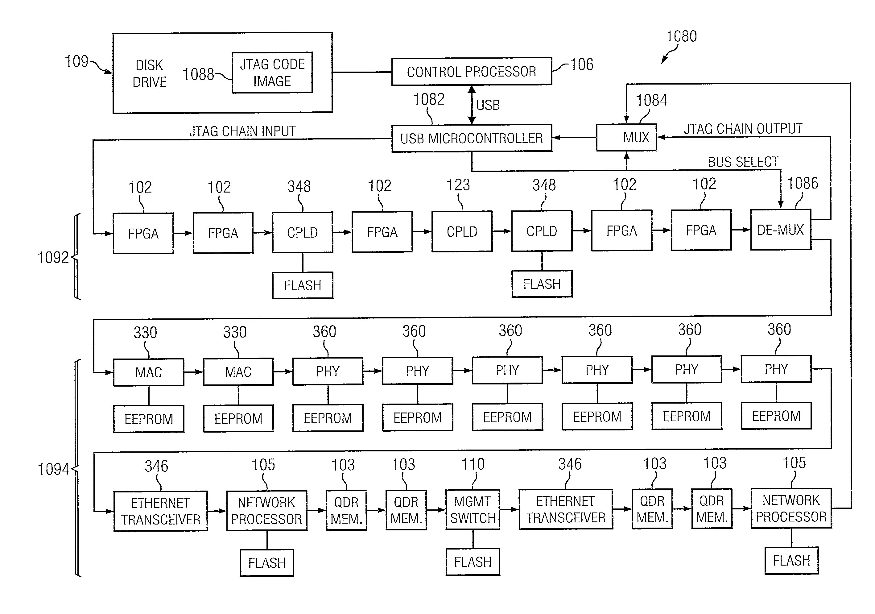
[0303]Controller 106 provides operational control of one or more blades in architecture 100A. Controller 106 includes control processor 134 coupled to an electrically erasable programmable read only memory (EEPROM) containing the basic input and output system (BIOS), universal serial bus (USB) interfaces 336, clock source 338, joint test action group (JTAG) controller 324, processor debug port 334, random access memory (RAM) 332, and Ethernet medium access controllers (MACs) 330A and 330B coupled to non-volatile memories 320 / 322. EEPROM memory 322 may be used to store general configuration options, e.g., the MAC address(es), link types, and other part-specific configuration options. Flash memory 320 may be used to store configurable applications such as network boot (e.g., PXE Boot).
[0304]Controller 10...
PUM
Abstract
A method of sending programming and debug commands, comprises loading control instructions on a processor from an attached tangible, non-transitory computer-readable medium, copying the contents of a program image file by the processor from the computer-readable medium across a bus to a programmable device on the same card as the processor, signaling the programmable device to send an instruction to a configurable logic device (CLD) on the same card as the processor via a debug channel.
Description
CROSS-REFERENCE TO RELATED APPLICATIONS[0001]This application is a member of a family of related U.S. Co-Pending applications filed Jun. 21, 2012, including: Ser. Nos. 13 / 529,207, 13 / 529,248, 13 / 529,289, 13 / 529,339, 13 / 529,372, 13 / 529,423, 13 / 529,479, 13 / 529,535, 13 / 529,575, 13 / 529,693, 13 / 529,745, 13 / 529,786 13 / 529,821, 13 / 529,859, 13 / 529,910, 13 / 529,932, 13 / 529,970, 13 / 529,983, 13 / 529,998, 13 / 530,019, 13 / 530,052, and 13 / 530,094, all of which applications are hereby incorporated by reference in their entirety.TECHNICAL FIELD[0002]The present disclosure relates to systems and methods for testing communications networks, services, and devices, e.g., testing the traffic-handling performance and / or security of the network, network accessible devices, cloud services, and data center services.BACKGROUND[0003]Organizations are increasingly reliant upon the performance, security, and availability of networked applications to achieve business goals. At the same time, the growing popularity ...
Claims
Application Information
Patent Timeline
Application Date:The date an application was filed.
Publication Date:The date a patent or application was officially published.
First Publication Date:The earliest publication date of a patent with the same application number.
Issue Date:Publication date of the patent grant document.
PCT Entry Date:The Entry date of PCT National Phase.
Estimated Expiry Date:The statutory expiry date of a patent right according to the Patent Law, and it is the longest term of protection that the patent right can achieve without the termination of the patent right due to other reasons(Term extension factor has been taken into account ).
Invalid Date:Actual expiry date is based on effective date or publication date of legal transaction data of invalid patent.