
Automated substance storage

a technology of automatic storage and substance, applied in the field of climate cabinets, can solve the problems of large amount of space left unoccupied, difficult to integrate processing devices in space-saving manner, etc., and achieve the effect of increasing the transport capacity

Active Publication Date: 2014-10-14
LICONIC
View PDF73 Cites 63 Cited by
  • Summary
  • Abstract
  • Description
  • Claims
  • Application Information

AI Technical Summary

Benefits of technology

The storage system described in this patent is suitable for small and medium-sized storages, as well as those with integrated processing devices. It is designed to optimize space and provide cost-effective solutions for transport mechanisms. The system includes a unique storage cabinet for laboratory material that allows for compact storage of microtitration plates. The storage system has several horizontally moveable supports that enable easy movement of storage sites. These supports can be moved to create a gap for a lift carriage, thus increasing the transport capacity in the horizontal direction. Overall, this storage system offers an efficient and versatile solution for laboratory material storage and retrieval.

Problems solved by technology

The disadvantage of the known systems is that either they are suitable exclusively for large storage facilities, or that they leave a large amount of space unused.
Furthermore, with the known arrangements it is not easy to integrate processing devices in a space-saving manner while maintaining the footprint.

Method used


Image

  • Automated substance storage
  • Automated substance storage
  • Automated substance storage

Examples


first embodiment

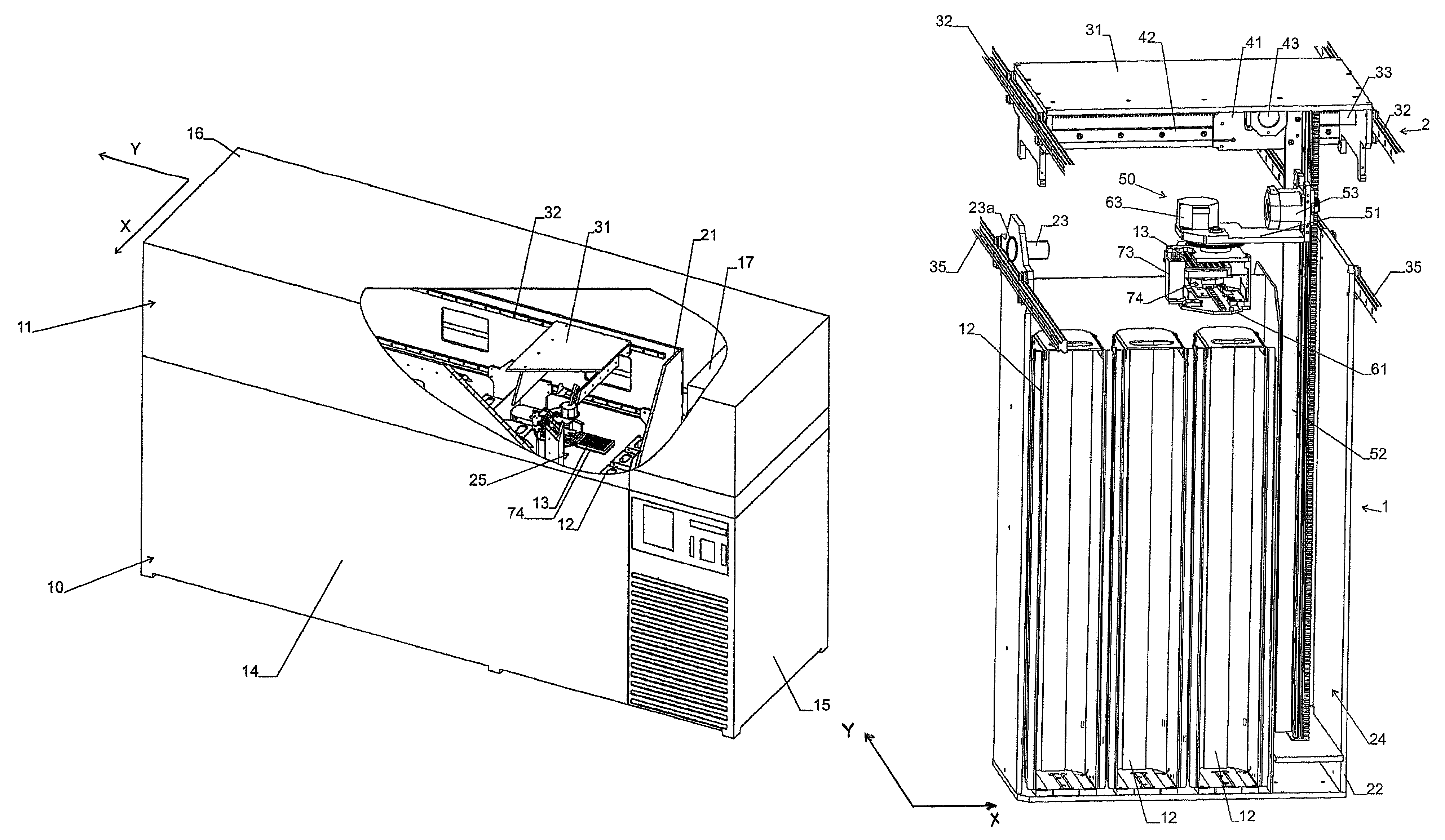
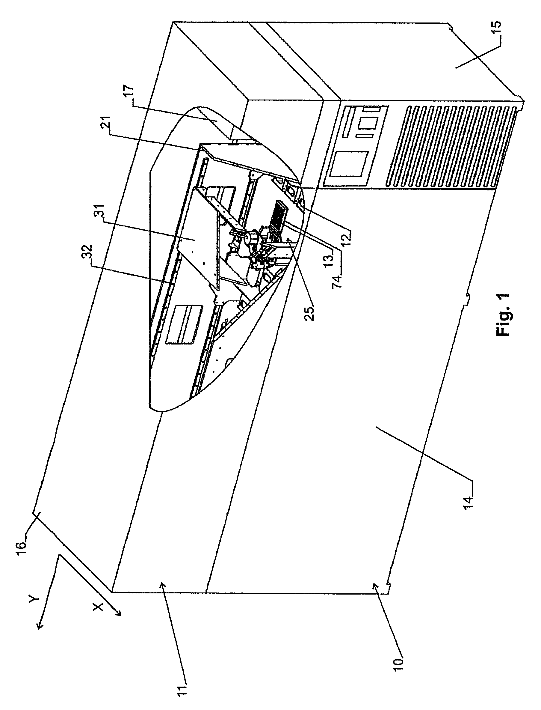
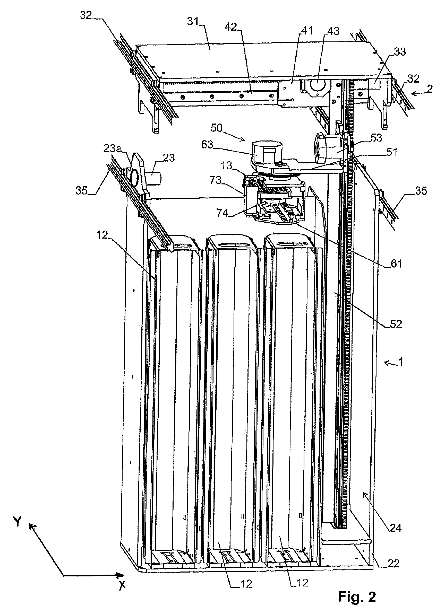
[0055]FIGS. 1 and 2 show a climatic cabinet with a lower zone 10 and an upper zone 11. The storage articles are stored in removable cassettes 12 in lower zone 10, which forms a storage zone of the device. Each cassette 12 provides space to accommodate several objects 13 to be stored one above the other. Objects 13 are preferably so-called microtitration plates. However, the present invention can also be used to store other laboratory articles, such as e.g., bottles, dishes, test tubes, etc.

[0056]In lower zone 10, the climatic cabinet forms a cooling vat 14, in which a low temperature is maintained by a refrigeration unit 15. A low-temperature storage is thus rendered possible, while the components in upper zone 11 are exposed to temperatures that are not as low.

[0057]Upper zone 11 is covered by a cover 16 and is likewise cooled, albeit to a temperature that is not as low. A dryer 17 is provided in upper zone 11 to extract moisture from the atmosphere within the climatic cabinet to p...

embodiment 10

[0089]As can be seen, lift column 52 in this case is supported on a longitudinal guide 32 in lower zone 10 and projects into upper zone 11. It supports lifting device 50 with rotary carriage 61. Lifting device 50 or lift column 52 is in turn horizontally displaceable, namely in direction Y as well as in direction X (where direction X is perpendicular to the drawing plane in FIG. 12). For the displacement in direction X, lift column 52 is supported on a longitudinal shift table 31, analogous to the embodiment 10.

[0090]A heater 112 is installed at least in the upper zone for heating.

[0091]Instead of the arrangement according to FIG. 12, for a high-temperature climatic cabinet an arrangement according to the embodiments according to FIGS. 3 through 6 can also be used (in this case, however, the carousels are arranged in the upper zone 11) or FIGS. 7 and 8 (with rotary elevators 101 arranged in the upper zone 11) or 11 (with cassettes 12 arranged in the upper zone 11).

[0092]It is noted ...


PUM


Abstract

A climatic cabinet and storage cabinet that includes an upper zone, a lower zone, storage positions for storing objects in one of the upper and lower zone, and at least one temperature control unit structured and arranged to maintain a temperature in the one of the upper and lower zone different from the other of the upper and lower zone. The cabinet further includes a lock, a horizontal transport mechanism arranged at least in part in the other of the upper and lower zone to move the objects to and from the lock in a direction having a horizontal component, and a vertical transport mechanism structured and arranged to move the objects between the lower zone and the upper zone.

Description

CROSS-REFERENCE TO RELATED APPLICATIONS[0001]The present application claims priority under 35 U.S.C. §119 of Swiss Patent Application No. 0441 / 07, filed Mar. 20, 2007, the disclosure of which is expressly incorporated by reference herein in its entirety.BACKGROUND OF THE INVENTION[0002]1. Field of the Invention[0003]The invention relates to a climatic cabinet or storage cabinet with an upper zone and a lower zone, and storage positions for storing objects in one of the lower and upper zone.[0004]2. Discussion of Background Information[0005]With the increasing degree of automation in medical engineering, there is a rising need to be able to manage substances from long-term storage automatically. To avoid chemical changes in the substances, they are often stored at the lowest temperatures possible. The temperature ranges below −80° C. are of increasing importance here. The transport of storage articles at these extremely low temperatures makes special demands on the mechanics and cont...

Claims


Application Information

Patent Timeline
Patent Type & Authority Patents(United States)
IPC IPC(8): F25D11/00A47B63/06B65G1/127B65G1/133F25D3/11F25D13/06F25D25/04
CPCF25D25/04F25D3/11F25D13/06A47B63/06B65G1/127B65G1/133A47B63/062A47B63/067A47B63/065
Inventor MALIN, COSMAS
Owner LICONIC
Learn More