Multiple staged compressor with last stage airfoil cooling

a compressor and air foil technology, applied in the direction of machines/engines, efficient propulsion technologies, liquid fuel engines, etc., can solve the problem that the cooling air foil cannot include the cooling air of the discharging film for the exterior surface, and achieve the effect of reducing the compression ratio, preventing overheating, and increasing the air temperatur

Inactive Publication Date: 2014-10-14
FLORIDA TURBINE TECH
View PDF1 Cites 69 Cited by
  • Summary
  • Abstract
  • Description
  • Claims
  • Application Information

AI Technical Summary

Problems solved by technology

Because the air pressure used for the cooling of the last stage airfoils is less than the external air flow pressure around these cooled air foils, the cooled air foils cannot include discharging film cooling air for cooling the exterior surface because of the differential pressure.

Method used


Image

  • Multiple staged compressor with last stage airfoil cooling
  • Multiple staged compressor with last stage airfoil cooling
  • Multiple staged compressor with last stage airfoil cooling

Examples


Embodiment Construction

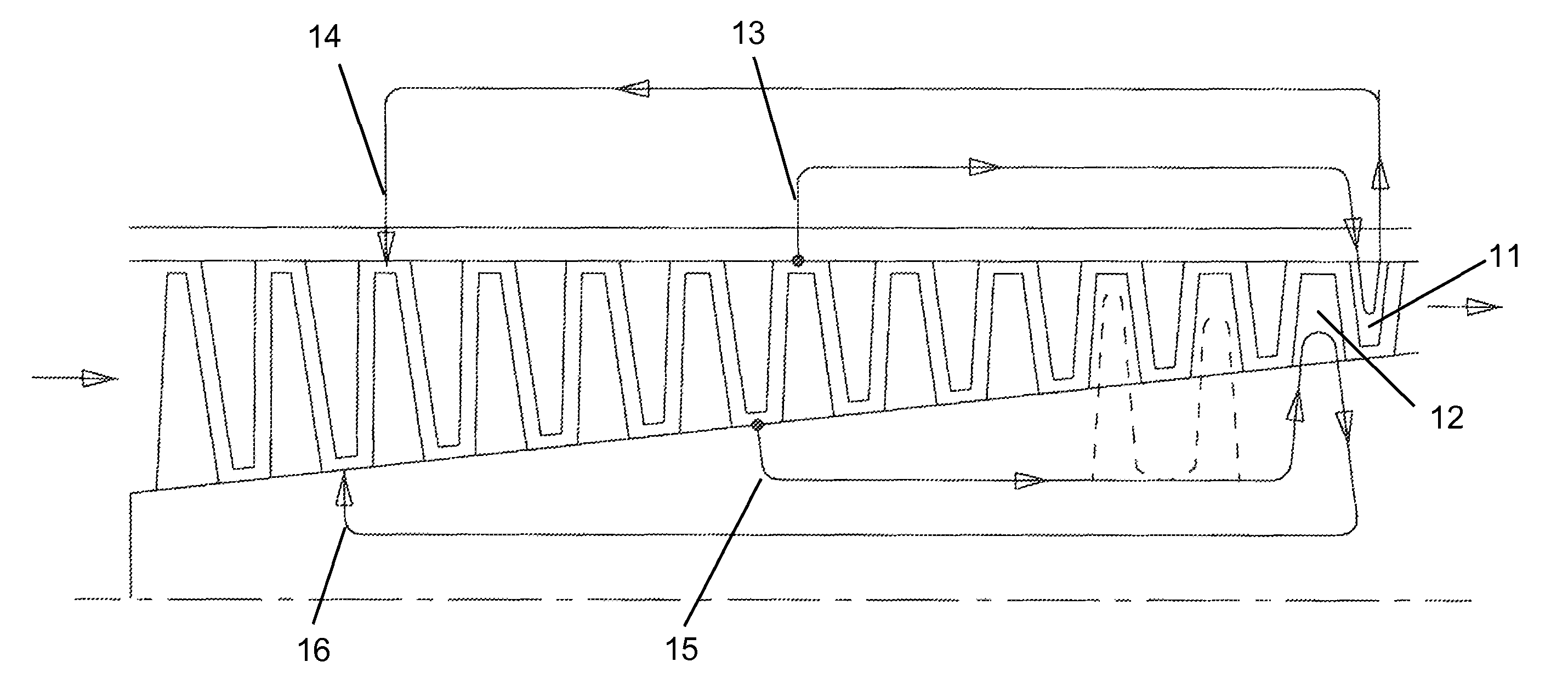
[0024]The present invention is a multiple stage compressor that produces a very high pressure ratio such that cooling of the last stage or stages of the compressor air required. The compressor is intended to be used in a gas turbine engine such as an aero engine or an IGT engine. However, the present invention could be used in any turbomachine in which a multiple stage compressor is used that produces the high pressure ratio in which cooling of the last stage airfoils is required to prevent thermal damage.

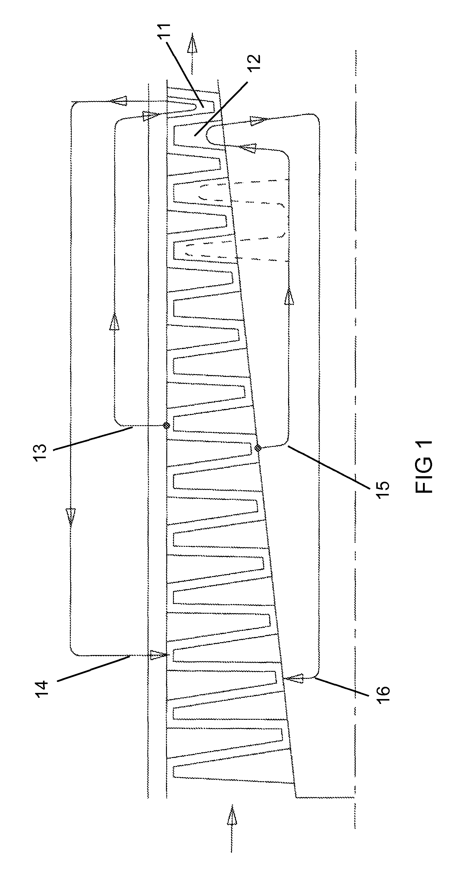
[0025]FIG. 1 shows a cross section of the compressor of the present invention in which a number of stages are present with each stage having a stator or guide vane located upstream from an associated rotor blade. In a typical multiple stage compressor of an aero engine, the outer diameter of the compressor is about at a constant radial diameter while the inner diameter is conical shaped with a decreasing airfoil spanwise height in the downstream direction. The inlet air to the comp...


PUM


Abstract

An industrial gas turbine engine in which a compressor includes later stage airfoils that are cooled using a coolant from an external closed loop cooling circuit or from a heat recovery steam generator. Cooling air compressed by a compressor external to the IGT engine can be used for cooling of the main compressor airfoils with a heat exchanger to preheat a fuel used in the combustor. Or, water and steam from a heat recover steam generator can be used to cool the compressor airfoils in which steam can be bled off from the steam generator for cooling and then reintroduced into the HRSG at a downstream stage. Steam is used to cool the rotor blades while water is used to cool the stator vanes.

Description

CROSS-REFERENCE TO RELATED APPLICATIONS[0001]This application is a CONTINUATION-IN-PART of U.S. patent application Ser. No. 13 / 946,003 filed on Jul. 19, 2013, now U.S. Pat. No. 8,721,265, and which is a CONTINUATION-IN-PART of U.S. patent application Ser. No. 13 / 904,629, now U.S. Pat. No. 8,794,907, filed on May 29, 2013 and entitled MULTIPLE STAGED COMPRESSOR WITH LAST STAGE AIRFOIL COOLING; which is a CONTINUATION-IN-PART of U.S. patent application Ser. No. 13 / 526,601, now U.S. Pat. No. 8,240,975, filed on Jun. 19, 2012 and entitled MULTIPLE STAGED COMPRESSOR WITH LAST STAGE AIRFOIL COOLING; which is a CONTINUATION-IN-PART of U.S. patent application Ser. No. 12 / 268,340, now U.S. Pat. No. 8,240,975, filed on Nov. 10, 2008 and entitled MULTIPLE STAGED COMPRESSOR WITH LAST STAGE AIRFOIL COOLING; which claims the benefit to U.S. Provisional Application 61 / 004,738 filed on Nov. 29, 2007.GOVERNMENT LICENSE RIGHTS[0002]None.BACKGROUND OF THE INVENTION[0003]1. Field of the Invention[0004]...

Claims


Application Information

Patent Timeline
Patent Type & Authority Patents(United States)
IPC IPC(8): F01D5/14F04D29/36F03D11/00F03B11/00F01D15/10F01D25/12
CPCF01D25/12F01D15/10F02C7/143F02C7/16F02C7/185F04D19/02F04D29/324F04D29/542F04D29/584F05D2220/3216F05D2220/3219F05D2260/213Y02T50/675Y02T50/60
Inventor RYZNIC, JOHN E.DOWNS, JAMES P.BROSTMEYER, JOSEPH D.
Owner FLORIDA TURBINE TECH
Why Eureka
Try Eureka