Isochoric heat addition engines and methods

a technology of isochoric heat addition and combustion engine, which is applied in the direction of liquid fuel engine, machines/engines, mechanical equipment, etc., can solve the problems of reducing the efficiency of engines designed to complete one cycle, preventing them from achieving higher levels of efficiency, and causing high compression in the compression chamber, so as to reduce the tangential flow of fluid and improve sealing

Active Publication Date: 2014-10-21
LIQUIDPISTON INC
View PDF158 Cites 25 Cited by
  • Summary
  • Abstract
  • Description
  • Claims
  • Application Information

AI Technical Summary

Benefits of technology

[0017]Another embodiment provides a system for sealing a rotor of an internal combustion engine in relation to a housing, the rotor having an edge and a face. The system of this embodiment includes a groove formed in the face of the rotor, proximate to the edge and having a radially inward wall and a radially outward wall, the groove having a bevel located in the radially outward wall; and a sealing strip disposed in the grove and having, in contact with the groove, a conformal surface. The strip is engaged in frictional contact against the housing, the housing presenting to the sealing strip a substantially flat surface, the friction tending to cause the strip to rotate slightly with respect to the rotor and to move slightly axially in a direction out of the groove, so as to reduce any gap between the strip and the housing and so as to increase sealing between the rotor and the housing.
[0020]In another embodiment, the present invention provides a sealing system for a rotary engine, and the embodiment includes a plurality of grooves formed in an interior surface of a housing wall, and a spring-loaded sealing strip disposed in each of the grooves; an orifice in the housing wall located between the grooves, the orifice coupled to an oil supply; and a floating cover disposed between the housing wall and a rotor of the engine. The floating cover has an inner face adjacent to a face of the rotor and an outer face adjacent to the interior surface of the housing wall. The inner face of the floating cover includes a groove having a diameter conforming generally to a diameter of the rotor, and a spring-loaded sealing strip located in the grove of the floating cover. The oil supply causes pressurized oil to apply an axial force to the outer face of the floating cover in opposition to axial forces on the inner face of the floating cover caused by a working medium of the engine so as to assist in sealing the engine.
[0024]In yet another embodiment, the invention provides a sealing system for improving sealing in a rotary engine between a first member that functions as one of a vane or gate, and capable of motion along an axis, and a second member moving with respect to the first member, the first member engageable against the second member at a limit of motion along the axis. The sealing system of this embodiment includes a matched pair of components, the matched pair serving as the first member. Each one of the matched pair is mounted so as to be separately movable along the axis of movement of the first member, so that each component may move differentially relative to the other component to improve sealing at the limit of motion of the components.
[0025]In yet another embodiment, the invention provides a rotor face seal, and the embodiment includes radial features such as ridges, dimples, strips radiated in a radial direction and disposed on a flat surface of the rotor; these features reduce tangential flow of the fluid across the flat face surface of the rotor.

Problems solved by technology

These cycles all have distinct characteristics, but each has disadvantages that prevent them from achieving higher levels of efficiency while maintaining high power outputs.
Increasing the efficiency of engines designed to complete one of these cycles has proven to be challenging.
In a conventional engine part of the challenge stems from the fact that all the processes such as compression, combustion and expansion, happen within the same space only at different times. Additional challenges stem from an inability to create high compression in the compression chamber and the inability to maintain the compressed volume at a constant volume over an interval sufficient to optimize combustion for various operating conditions or loads.
Furthermore, with the exception of the Atkinson cycle, which is not completed in a typical combustion engine, efficiency is loss because the expansion cycle is prematurely ended before the products of the combustion process are exhausted and replaced with a fresh intake.

Method used


Image

  • Isochoric heat addition engines and methods
  • Isochoric heat addition engines and methods
  • Isochoric heat addition engines and methods

Examples


Embodiment Construction

Definitions

[0071]As used in this description and the accompanying claims, the following terms shall have the meanings indicated, unless the context otherwise requires:

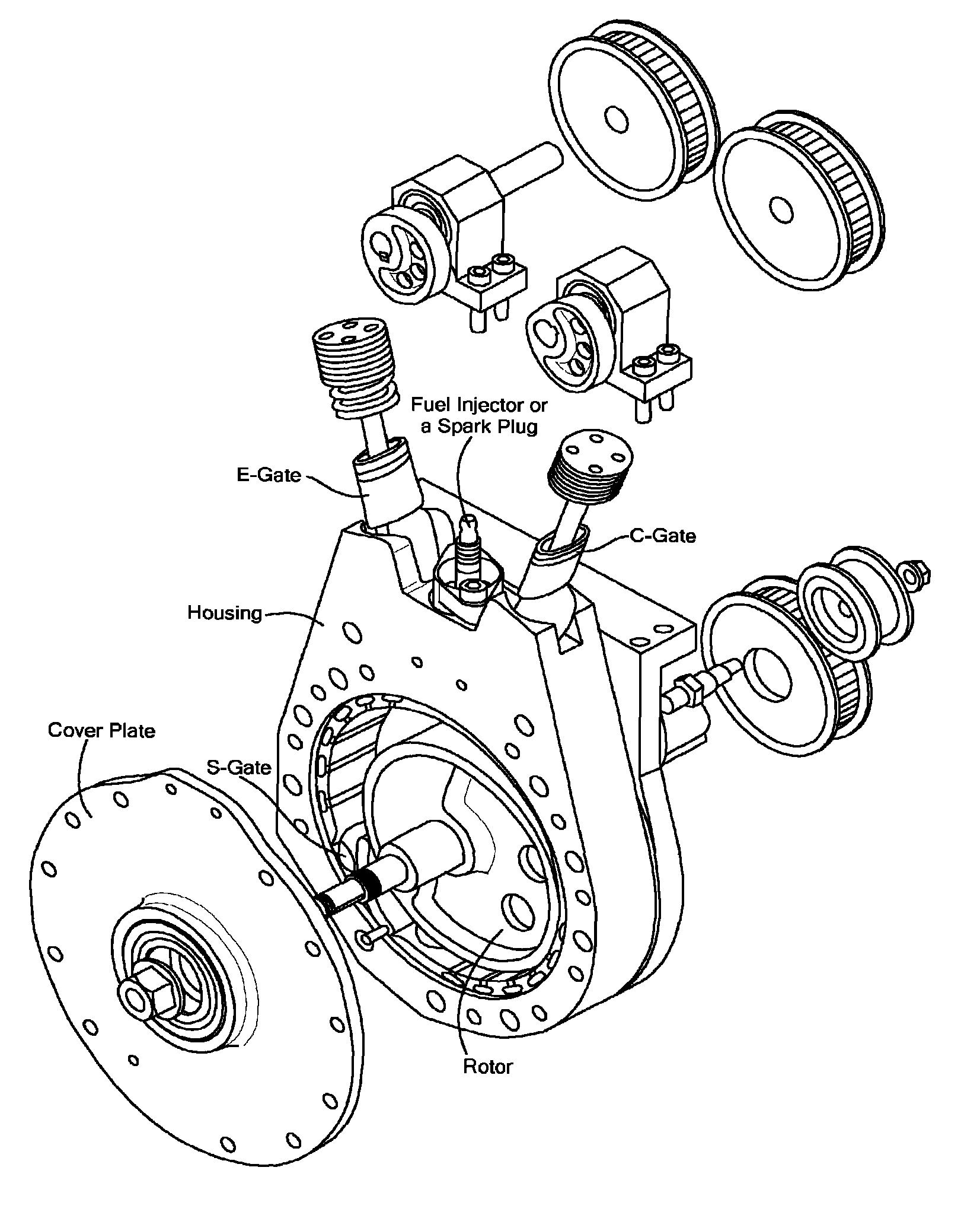
[0072]A “rotor” is a structure, rotatably mounted in a housing that transmits torque, developed as a result of combustion, to a mechanical output.

[0073]A “gate” is a movable structure, for partitioning a volume, that is periodically or continuously in contact with a member, such as a rotor, that is moving with respect thereto. A gate may move with a rotating or translating motion, and such motion need not substantially change the volume of a relevant cavity.

[0074]A “vane” is a movable structure, motion of which causes displacement of a volume, that also has a partitioning function and is periodically or continuously in contact with a member, such as a rotor or a housing that is moving with respect thereto.

[0075]A “piston” is a mass moving linearly with respect to a housing in which it is located and that transmits forc...


PUM


Abstract

Engines and methods execute a high efficiency hybrid cycle, which is implemented in a volume within an engine. The cycle includes isochoric heat addition and over-expansion of the volume within the engine, wherein the volume is reduced in a compression portion of the cycle from a first quantity to a second quantity, the volume is held substantially constant at the second quantity during a heat addition portion of the cycle, and the volume is increased in an expansion portion of the cycle to a third quantity, the third quantity being larger than the first quantity.

Description

CROSS REFERENCE TO RELATED APPLICATIONS[0001]The present application also claims priority to U.S. Provisional Application Nos. 61 / 085,928, 61 / 149,889, 61 / 154,539 61 / 184,627, and 61 / 219,495 filed respectively on Aug. 4, 2008, Feb. 4, 2009, Feb. 23, 2009, Jun. 5, 2009, and Jun. 23, 2009. Each of the foregoing applications is hereby incorporated herein by reference herein in its entirety.TECHNICAL FIELD[0002]The present invention relates to internal combustion engines, and more particularly to internal combustion engines completing a high efficiency hybrid cycle.BACKGROUND ART[0003]It is known in the prior art to run internal combustion engines on cycles such as a Diesel cycle, an Otto cycle, or an Atkinson cycle. These cycles all have distinct characteristics, but each has disadvantages that prevent them from achieving higher levels of efficiency while maintaining high power outputs. Increasing the efficiency of engines designed to complete one of these cycles has proven to be challen...

Claims


Application Information

Patent Timeline
Patent Type & Authority Patents(United States)
IPC IPC(8): F01C1/344F02B53/10F01C1/356F01C1/32F01C1/00F01C1/328F01C21/08F02B53/00F01C1/20F01C9/00B05D3/04F02B43/00
CPCF01C1/328F01C1/3446F01C1/3562F01C1/3443F01C21/0836F01C9/002F01C1/322F01C1/20F01C21/0809F02D1/065F02B33/40Y02T10/12F01C1/344F02B53/00F02B55/02F02B55/08F02B53/14
Inventor SHKOLNIK, NIKOLAYSHKOLNIK, ALEXANDER C.
Owner LIQUIDPISTON INC
Why Eureka
Try Eureka