Alternator for vehicle with heat dissipating fin

a technology of heat dissipation fin and alternator, which is applied in the direction of magnetic circuit rotating parts, magnetic circuit shape/form/construction, windings, etc., can solve the problems of reducing the production cost of the rectifier, and achieve the effect of facilitating the control of the sub-fin, and reducing the production cos

Active Publication Date: 2014-10-21
DENSO CORP
View PDF23 Cites 0 Cited by
  • Summary
  • Abstract
  • Description
  • Claims
  • Application Information

AI Technical Summary

Benefits of technology

[0008]It is an object of this disclosure to provide an alternator with a heat dissipator which is simple in structure and ensures a desired degree of cooing ability to cool a rectifier.

Problems solved by technology

The press forming of the sub-fins results in no burr between adjacent two of the sub-fins, thereby eliminating the need of an additional process of finishing the sub-fins, which leads to a decrease in production cost of the rectifier.

Method used


Image

  • Alternator for vehicle with heat dissipating fin
  • Alternator for vehicle with heat dissipating fin
  • Alternator for vehicle with heat dissipating fin

Examples


Embodiment Construction

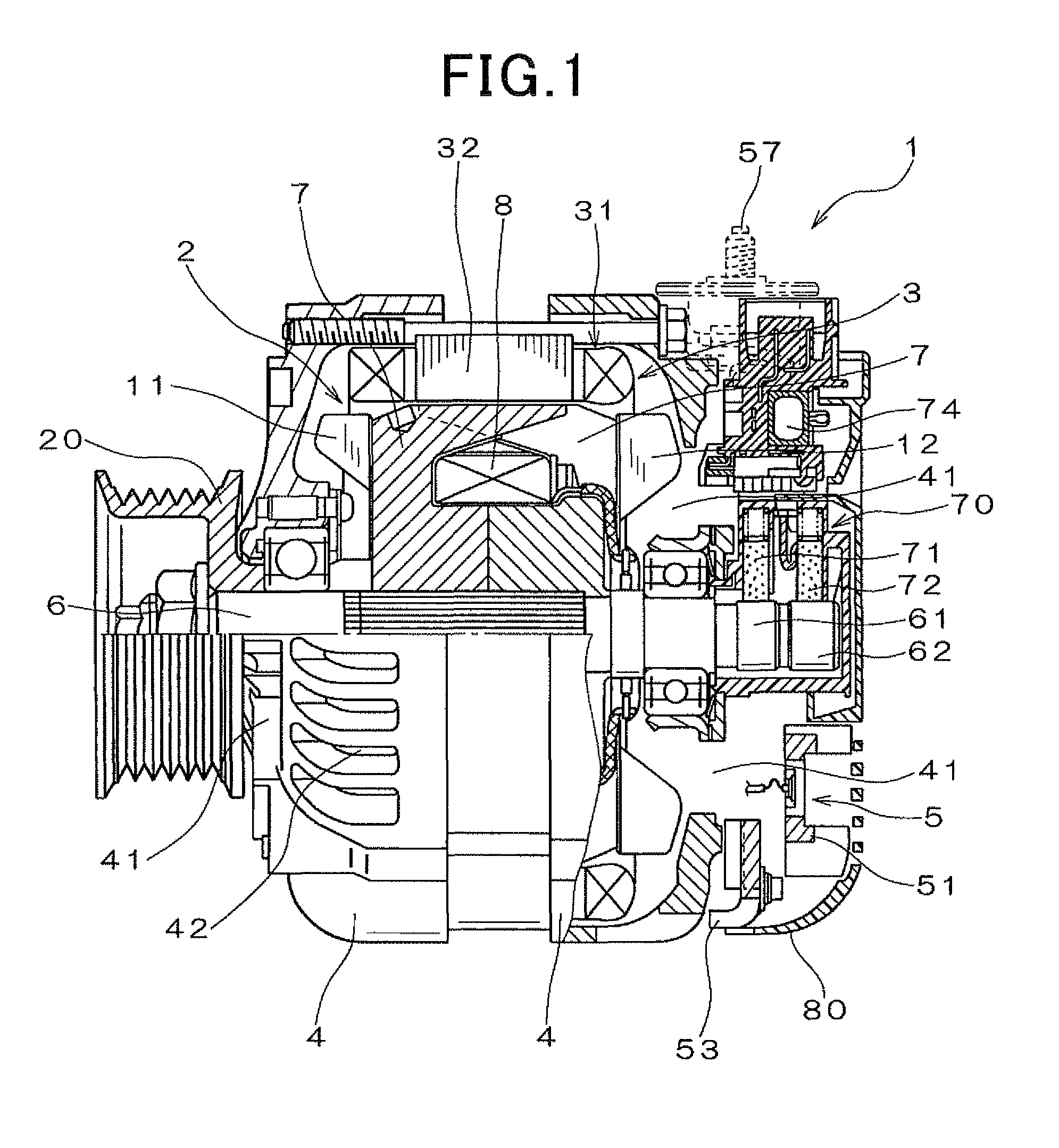
[0040]Referring to the drawings, wherein like reference numbers refer to like parts in several views, particularly to FIG. 1, there is shown an AC generator or alternator 1 for automotive vehicles according to the first embodiment.

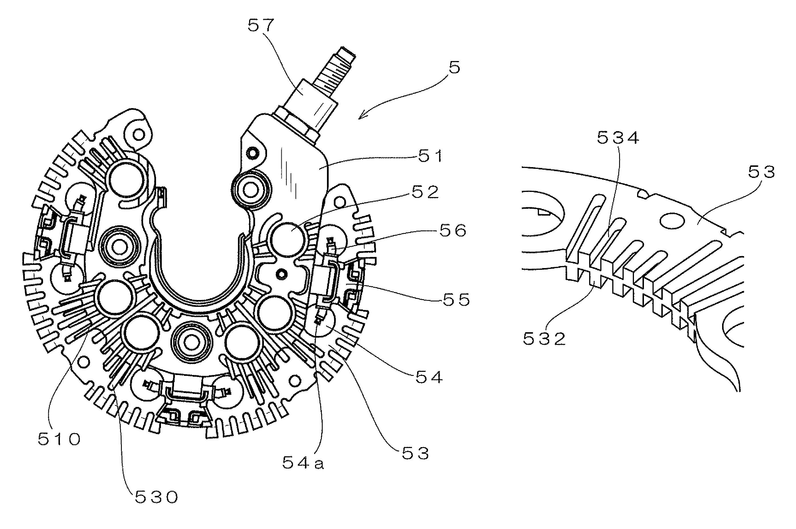
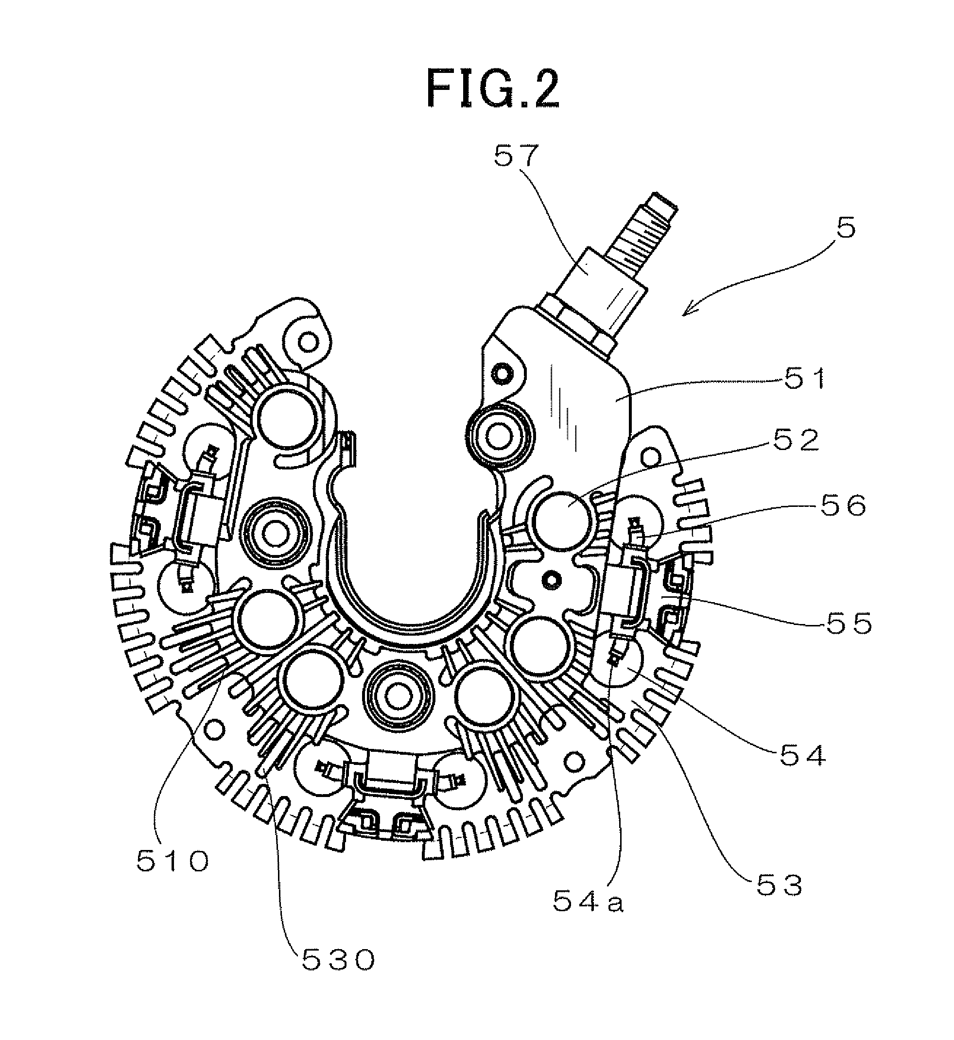
[0041]The alternator 1 consists essentially of a rotor 2, a stator 3, a frame assembly 4, and a rectifier 5.

[0042]The rotor 2 is, as clearly shown in FIG. 1, made up of a pair of pole cores 7 with claws and a field coil 8 retained between the pole cores 7. The field coil 8 is made of copper wire which is coated with an insulator and wound coaxially in the form of a cylindrical shape. A rotating shaft 6 is inserted through the pole cores 7. A cooling fan 11 is welded to an end wall of a front one (i.e., a left one, as viewed in FIG. 1) of the pole cores 7. The cooling fan 11 works to suck air from the front of the alternator 1 and discharge it axially and radially of the alternator 1. Similarly, a centrifugal fan 12 is welded to an end wall of a rear one of...


PUM


Abstract

An alternator for a vehicle is provided which is equipped with a heat dissipator and a cooling air generator. The heat dissipator is disposed in a rectifier to cool rectifying devices. The cooling air generator generates a flow of cooling air to the heat dissipator. The heat dissipator has a plurality of sub-fins formed thereon. Each of the sub-fins is defined by a combination of a protrusion and a recess. The protrusions are formed on one of opposed major surfaces of the heat dissipator, while the recesses are formed on the other major surface, one in coincidence with each of the protrusions in a thickness-wise direction of the heat dissipator. This permits the heat dissipator to be pressed to form the protrusions and the recesses to make the sub-fins simultaneously, thus allowing a heat-dissipating area to be increased to ensure a desired degree of heat capacity thereof.

Description

CROSS REFERENCE TO RELATED DOCUMENT[0001]The present application claims the benefit of Japanese Patent Application Nos. 2011-138999 and 2012-20877 filed on Jun. 23, 2011 and Feb. 2, 2012, disclosures of which are incorporated herein by reference.BACKGROUND OF THE INVENTION[0002]1. Technical Field of the Invention[0003]The present invention relates generally to an alternator which may be installed in passenger automobiles or trucks, and more particularly to such an alternator having installed therein a heat dissipator which is equipped with heat dissipating fins.[0004]2. Background Art[0005]Typical automotive alternators are equipped with a rectifier which has a positive-side fin radiator and a negative-side fin radiator to cool rectifying devices installed on the positive-side and negative-side fin radiators. Japanese Patent Publication No. 3775235 teaches such fin radiators with circular or elongated holes which are formed by a press to increase heat dissipating area of the fin rad...

Claims


Application Information

Patent Timeline
Patent Type & Authority Patents(United States)
IPC IPC(8): H02K11/04H02K9/06
CPCH02K11/046H02K9/06H02K11/05
Inventor KONAYA, KAZUYOSHIHAMADA, HIROSHIMASHINO, MIKIOKONDOH, SEIJI
Owner DENSO CORP
Why Eureka
Try Eureka