Lower limb joint orthosis and control method therefor

a technology for lower limb joints and orthotics, applied in the field of lower limb joint orthosis, can solve the problems of not being provided, unable to bend and stretch the ankle, and difficult or impossible to walk independently, so as to increase the sensitivities, reduce the size, and increase the output

Active Publication Date: 2014-10-28
HASHIMOTO ARTIFICIAL LIMB MFG CORP
View PDF11 Cites 14 Cited by
  • Summary
  • Abstract
  • Description
  • Claims
  • Application Information

AI Technical Summary

Benefits of technology

[0009]It is an object of the present invention to, by further improving the invention of Patent Literature 2 described above, make the structure compact by simplifying it, and also enable a sensitive operation and a high output.
[0013]In the invention, an MR fluid cylinder is a rotary cylinder including a plurality of fluid chambers in which an MR fluid is enclosed. This makes it possible to increase the sensitivities of a locked state and a free state of an orthotic ankle joint that are obtained by changing the viscosity of the MR fluid, increase the output, and reduce the size. Further, the adjustment of the viscosity of the MR fluid is made by the magnetic force of the electromagnet. This simplifies the structure and also facilitates the control. In the invention, an MR cylinder is a reciprocating cylinder. This simplifies the structure. Based on the invention, it is possible to automatically control the rotational resistance of a lower component and an upper component in accordance with the state of the bending and stretching of the ankle in the orientation of the leg during walking. This makes it possible to achieve a motion close to that of the ankle joint of a living body.

Problems solved by technology

In either case, it is often difficult or impossible to walk independently.
A joint function, however, is not provided, and therefore, it is not possible to bend and stretch the ankle in accordance with the shift of the center of the body weight, or absorb shock when the sole makes contact with the ground.
Accordingly, walking with the aid attached places a large burden on the body.
This causes a paralyzed person to avoid walking independently with the aid attached, or walking with minor assistance.
Consequently, also the walking function fails to be improved.
In this prior example, however, the orthosis for assisting independence is merely provided with a rotational movement function, and the range of rotational movement is limited to a very narrow range, which does not correspond to a wide angle from landing to stepping.
Further, although the locking and unlocking of a hinge mechanism is incorporated, the operation of the hinge mechanism requires the operation of a locking member, which is complicated and cumbersome.
This technique, however, tends to complicate the structure of the lower-limb joint orthosis, and increase the size of the lower-limb joint orthosis.

Method used


Image

  • Lower limb joint orthosis and control method therefor
  • Lower limb joint orthosis and control method therefor
  • Lower limb joint orthosis and control method therefor

Examples


Embodiment Construction

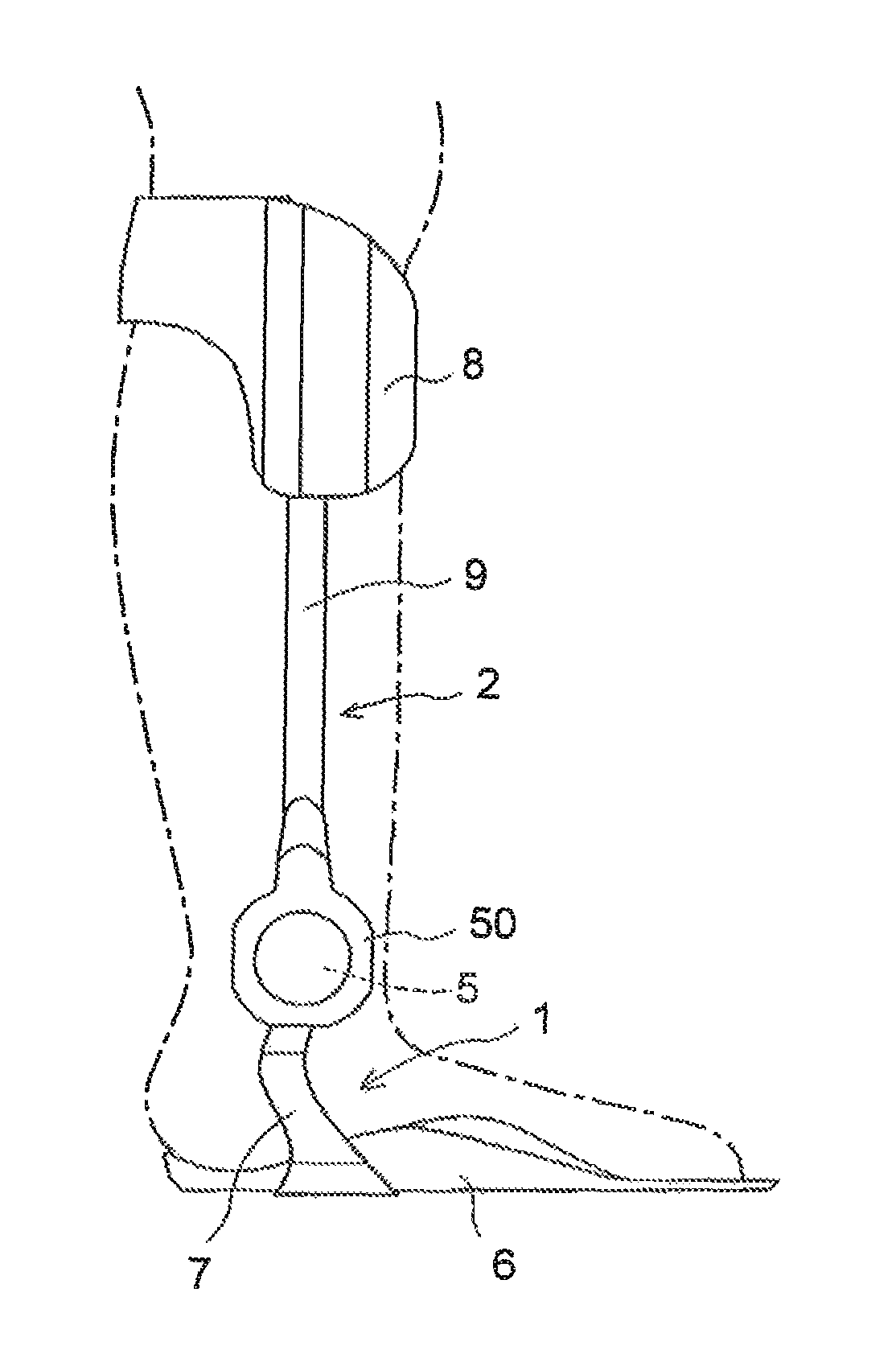
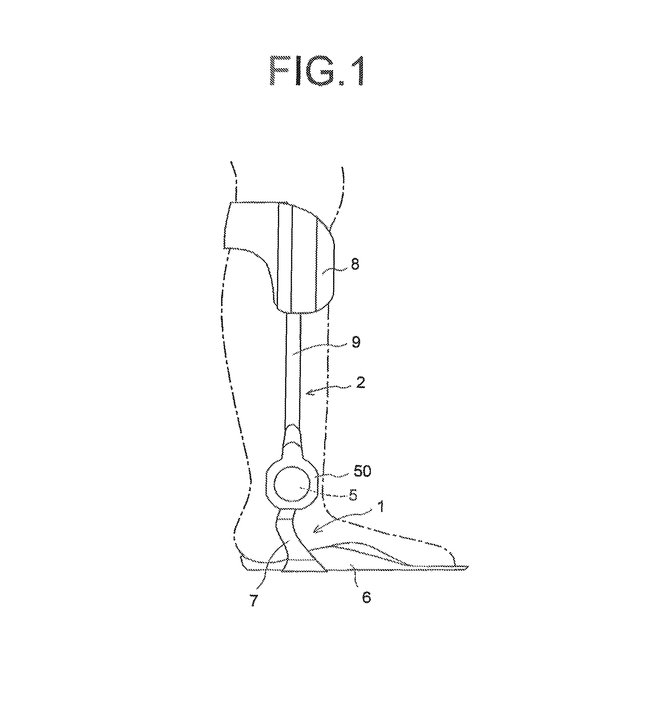
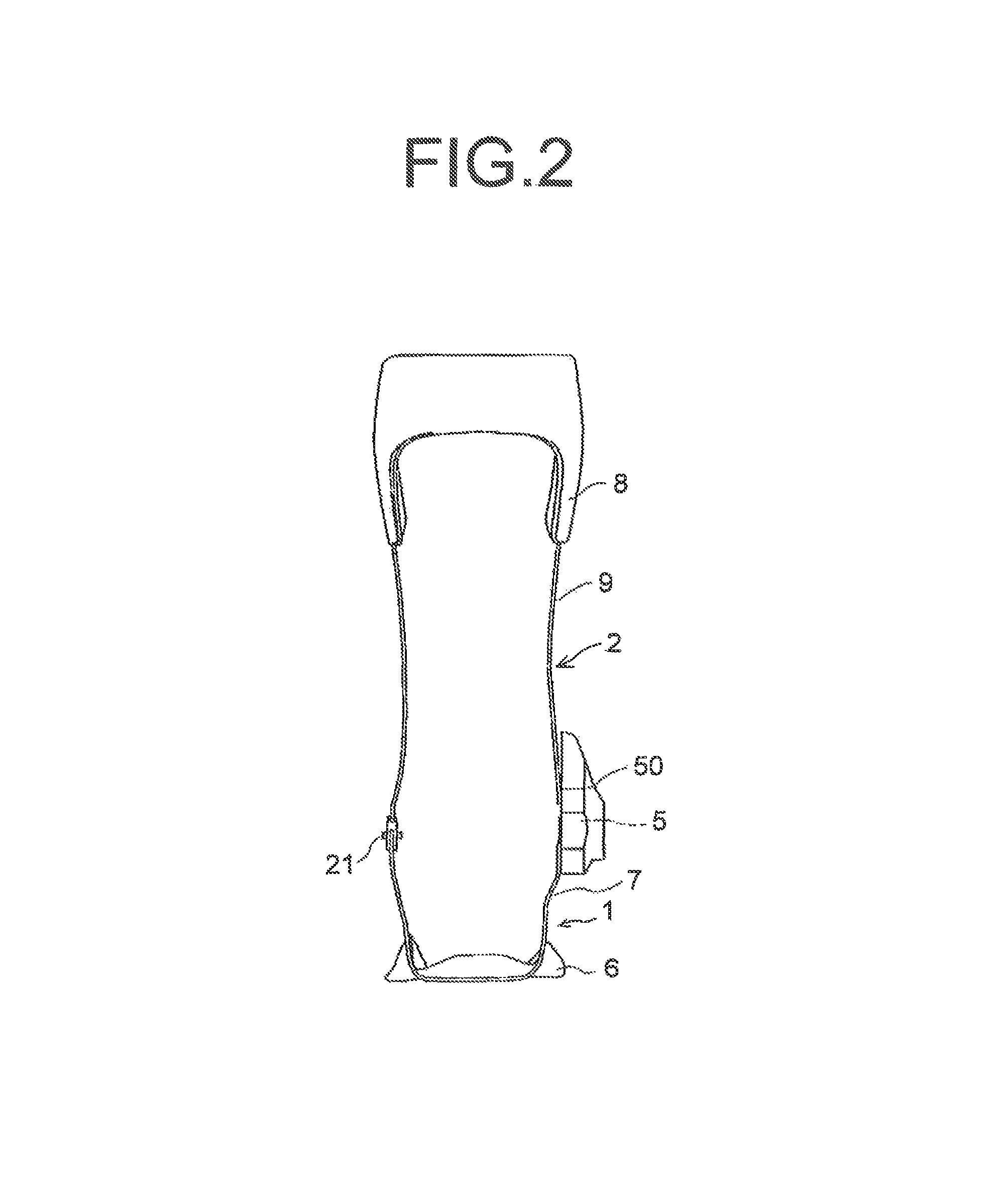
[0027]With reference to the drawings, a description is given below of embodiments of the present invention. FIG. 1 is a side view of a lower-limb joint orthosis provided with an ankle-joint function according to a first embodiment of the present invention; FIG. 2 is a rear view thereof; FIG. 3 is a vertical cross-sectional view of an orthotic joint included in the lower-limb joint orthosis; FIG. 4 is a right side view thereof; FIG. 5 is a left side view thereof; and FIG. 6 is a horizontal cross-sectional view thereof.

[0028]In the lower-limb joint orthosis (hereinafter also referred to simply as an “orthosis”) according to the present embodiment, an MR fluid cylinder is a rotary cylinder. The lower-limb joint orthosis includes a lower component 1, an upper component 2, and an orthotic joint 5 that couples the lower component 1 and the upper component 2 together. The lower component 1 is capable of supporting the sole mounted thereon; the upper component 2 is to be attached to the low...


PUM


Abstract

A lower-limb joint orthosis includes a lower component supporting the foot region, an upper component attached to the lower-limb, and an orthotic joint coupling both components. The orthotic joint includes: a stator including some fluid chambers in which an MR fluid is enclosed; and a rotor including partition plates protruding into the respective fluid chambers. The stator includes a communication path between the anterior chamber and the posterior chamber. The rotor includes connection paths that connect the anterior chambers together, and connect the posterior chambers together. An electromagnet is placed on a side surface of the communication path so that a rotational resistance of the lower component and the upper component is adjusted by adjusting a magnetic force to control the viscosity of the MR fluid that flows through the communication path.

Description

CROSS-REFERENCE TO RELATED APPLICATION[0001]This Application is a 371 of PCT / JP2010 / 005746 filed on Sep. 22, 2010 which, in turn, claimed the priority of Japanese Patent Application No. 2009-220326 filed on Sep. 25, 2009, both applications are incorporated by reference herein.BACKGROUND OF THE INVENTION[0002]1. Field of the Invention[0003]The present invention relates to a lower-limb joint orthosis suitable for use by a paralyzed person whose lower-limb, particularly foot region, is paralyzed, and also relates to a control method therefor.[0004]2. Description of the Related Art[0005]The forms of paralysis of the foot region include: hemiplegia in which mainly one foot is paralyzed due, for example, to apoplexy; and paraplegia in which, in many cases, both feet are paralyzed due, for example, to a spinal cord injury. In either case, it is often difficult or impossible to walk independently. Accordingly, when a person with such a paralysis walks, they need some aid. A conventional aid...

Claims


Application Information

Patent Timeline
Patent Type & Authority Patents(United States)
IPC IPC(8): A61F5/00A61F2/72
CPCA61F2005/0169A61F5/0125A61F5/0127
Inventor TOMIYAMA, HIROKIKUBO, TOMIO
Owner HASHIMOTO ARTIFICIAL LIMB MFG CORP
Why Eureka
Try Eureka