System and method for cardiac valve repair and replacement

a technology for cardiac valves and systems, applied in the field of system and method, can solve problems such as obstructing blood flow, mitral stenosis, and insufficiency, and achieve the effects of reducing the risk of cardiac valve damage, and improving the quality of li

a technology for cardiac valves and systems, applied in the field of system and method, can solve problems such as obstructing blood flow, mitral stenosis, and insufficiency, and achieve the effects of reducing the risk of cardiac valve damage, and improving the quality of li

US8870948B1Active Publication Date: 2014-10-28CEPHEA VALVE TECH

Image

  • System and method for cardiac valve repair and replacement
  • System and method for cardiac valve repair and replacement
  • System and method for cardiac valve repair and replacement

Examples


Embodiment Construction

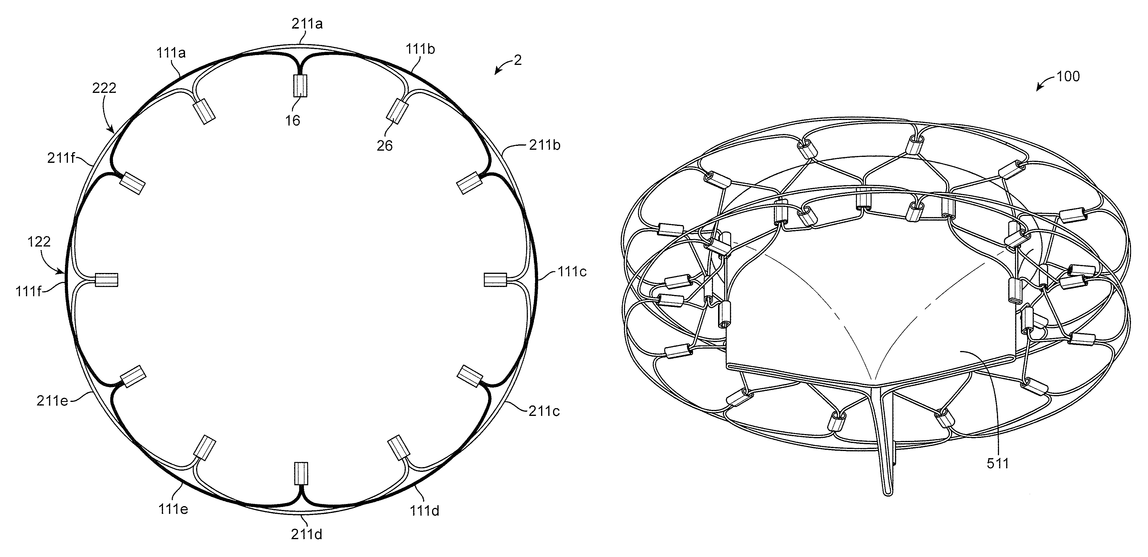
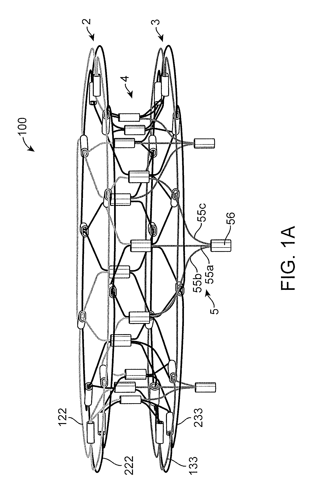
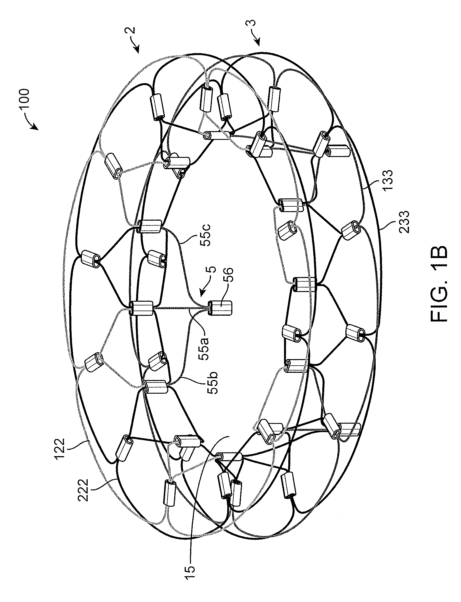
[0034]Described herein is a flexible, self-orienting cardiac valve prosthesis configured to be delivered through minimally invasive techniques. The prosthesis can include a proximal anchor (e.g., configured to be placed in the ventricle), a distal anchor (e.g., configured to be placed in the atrium), a central portion or column between the anchors, a plurality of struts extending distally (e.g., into the ventricle), and a plurality of leaflets attached to the struts. The prosthesis can be self-expanding, such as be made of super elastic nickel titanium (nitinol). In some embodiments, the prosthesis can be made of woven stranded nitinol.

[0035]The prosthesis described herein can be delivered to a cardiac valve orifice, such as the mitral valve, by using minimally invasive techniques to access cardiac valves through small incisions in the patient's body, passing the prosthesis through the apex of the heart, through the aorta via femoral artery access, through the aorta via an intercost...


PUM


Abstract

A prosthetic mitral valve includes a proximal anchor, a distal anchor, and a central portion therebetween. The proximal and distal anchors each include a first outer frame and a second outer frame. The first outer frame includes a plurality of first arcs joined together, and the second outer frame includes a plurality of second arcs joined together. The plurality of first arcs are out of phase relative to the plurality of second arcs.

Description

CROSS REFERENCE TO RELATED APPLICATIONS[0001]This application claims priority to U.S. Patent Provisional Application No. 61 / 847,515, filed on Jul. 17, 2013, entitled “SYSTEM AND METHOD FOR CARDIAC VALVE REPAIR AND REPLACEMENT,” the entirety of which is incorporated by reference herein.INCORPORATION BY REFERENCE[0002]All publications and patent applications mentioned in this specification are herein incorporated by reference to the same extent as if each individual publication or patent application was specifically and individually indicated to be incorporated by reference.FIELD OF INVENTION[0003]The present invention relates generally to the treatment of cardiac valve disorders, such as mitral valve replacement, using minimally invasive techniques.BACKGROUND[0004]The mitral valve lies between the left atrium and the left ventricle of the heart. Various diseases can affect the function of the mitral valve, including degenerative mitral valve disease and mitral valve prolapse. These d...

Claims


Application Information

Patent Timeline
28 Oct 2014
Publication
US8870948B1
IPC
A61F2/24
CPC
A61F2/2445; A61F2/2412; A61F2/2409; A61F2/2418; A61F2/2436; A61F2/2439; A61F2230/0065; A61F2220/0008
Inventors
ERZBERGER, GARY; CORCORAN, MICHAEL P.