Radar signature database validation for automatic target recognition

a technology of automatic target recognition and signature database, applied in the field ofradar signature analysis, can solve the problems of difficult computation of signatures with sufficient accuracy, difficult validation, and inability to meet the requirements of target recognition algorithms,

Inactive Publication Date: 2014-10-28
THE UNITED STATES OF AMERICA AS REPRESETNED BY THE SEC OF THE AIR FORCE
View PDF22 Cites 29 Cited by
  • Summary
  • Abstract
  • Description
  • Claims
  • Application Information

AI Technical Summary

Problems solved by technology
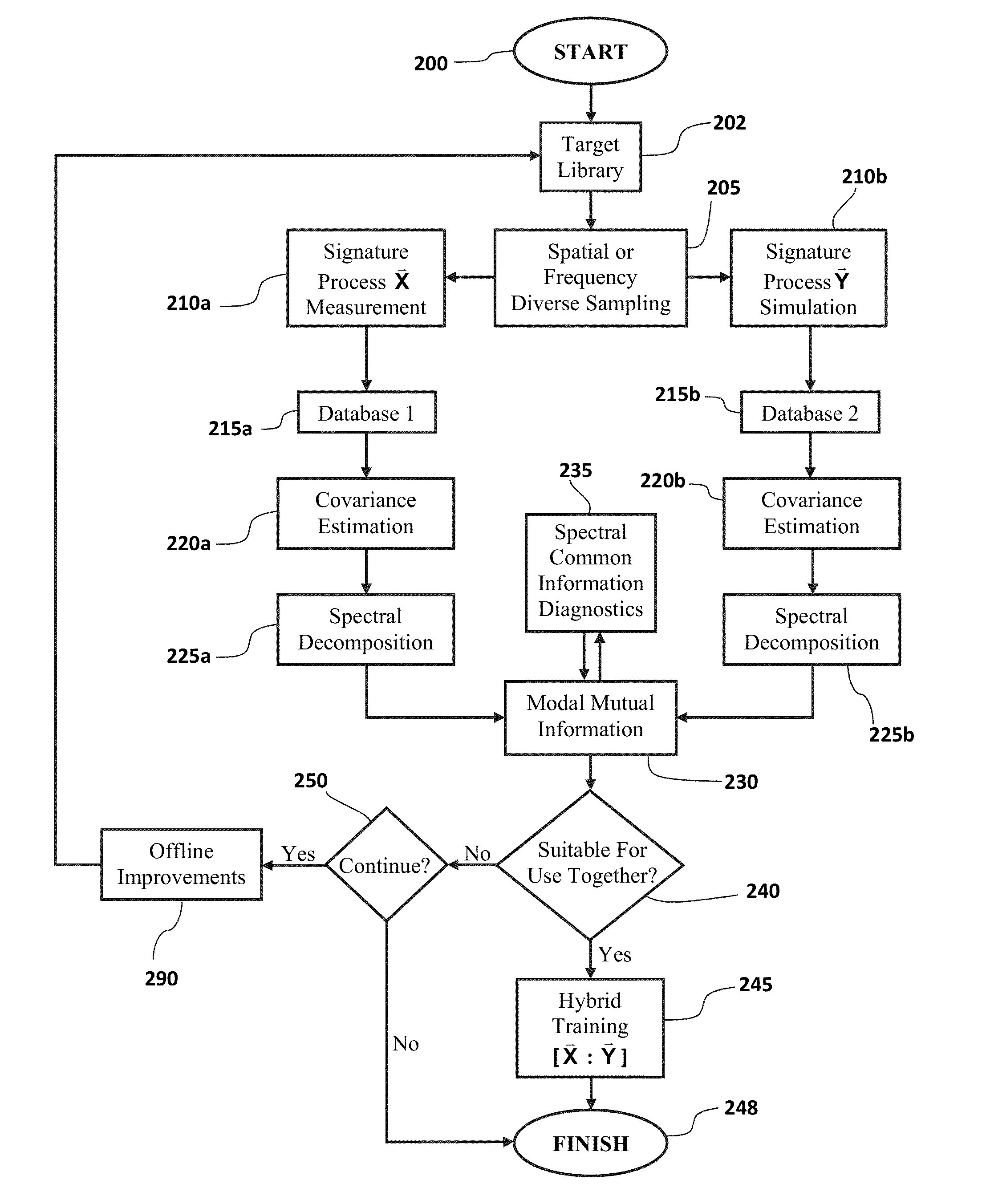
Construction of a signature database based entirely on measurements is expensive and can be an impractical proposition.
However, given the complexity of typical targets including personnel carriers, tanks, aircraft, and missiles, etc., and the challenge of modeling a variety of electromagnetic scattering phenomena ranging from specular reflection to edge diffraction, smooth surface diffraction etc., computation of signatures with sufficient accuracy is a challenging task.
The problem of validation is quite different from the design of target recognition algorithms.
Unlike the automatic target recognition problem, the database similarity problem (validation) involves the comparison of two random signature processes.

Method used


Image

  • Radar signature database validation for automatic target recognition
  • Radar signature database validation for automatic target recognition
  • Radar signature database validation for automatic target recognition

Examples


example 1

BTR-70 Vs. BMP2 (Out-of-Class Variations)

[0148]Example 1, which corresponds to case-1 and case-2 of Table 1, pertains to two targets (BTR-70 and BMP2) drawn from two different target classes. The mutual information between the signatures of dissimilar targets would be expected to be low as these signatures would be statistically independent. In FIG. 8, the MMI for the ‘out-of-class’ target case yields consistently low mutual information across the modes, and the total mutual information is also quite low at approximately 0.4 Nats. Confirming expectations, this low value of mutual information is consistent with the degree of statistical independence to be expected when the signature processes of two very dissimilar scattering sources (targets) are compared.

[0149]In the case-2 experiment of Table 1, the previous experiment is extended to conditions where current classification algorithm approaches (those based on geometric measure) indicate that the two targets drawn from two differen...

example 2

BTR-70 (In-Class Variations)

[0150]Example 2 corresponds to case-3 and case-4 in Table 1. Two targets from the same class are often similar but not identical. The physical differences can be minor or quite striking A number of experiments pertaining to the MMI and cumulative MI of in-class targets with different degrees of variations are considered. Case-3 of Table 1 corresponds to the signatures of the BTR-70 with and without the PEC ground plane representing a “minor” difference. For this case, the mutual information is expected to be high and is so demonstrated by the results shown in FIG. 10, with the cumulative MI at 10.5 Nats. FIG. 10 shows MMI and cumulative MI for BTR-70 with ground plane & BTR-70 without ground plane, a similar target case.

[0151]The target signature may be considered to be the sum of scattering from a collection of scattering centers. Variations in target and signatures, ranging from “marginal” to “major,” can be simulated by including or excluding chosen gr...

example 3

T-72 (In-Class Variations)

[0153]Example 3 corresponds to case-5 in Table 1. In-class variations from the baseline geometry may be obtained by removing certain physical features, and an effort is made to ensure that the scattering from these features is “persistent” over the whole target aspect angle window. The T-72 tank is used as the baseline target in the experiments designated as case-5 in Table 1 with three specific geometry components identified for study. The geometry components identified are the forward fenders, rear fuel barrels, and the gun barrel. The scattering from the front fender is eliminated, and FIGS. 12A and 12B illustrate the two dimensional image of the T-72 tank with and without the fender scattering. The reduction in resolved signal power within the cells associated with this geometry indicates the significant effect of eliminating the fender scattering. The results of this first of these sub-experiments are presented in FIG. 13 where the MMI is computed for ...


PUM


Abstract

An information theoretic method for testing and / or validating the suitability of a multi-radar signature database to be used on radar systems having automatic target recognition. The database may include measured data and / or modeled synthetic data. The technique allows measured data to be compared to the synthetic data using modal mutual information. The present invention further includes an information theoretic method for real time calculation of automatic target recognition using modal mutual information calculation.

Description

CROSS-REFERENCE TO RELATED APPLICATIONS[0001]This application is a continuation-in-part of U.S. patent application Ser. No. 12 / 770,211 filed on Apr. 29, 2010, which further claims the benefit of U.S. Provisional Application Ser. No. 61 / 173,694 filed on Apr. 29, 2009, both of which are entitled “Radar Signature Database Validation for Automatic Target Recognition” and both of which are hereby incorporated herein by reference in their entirety.RIGHTS OF THE GOVERNMENT[0002]The invention described herein may be manufactured and used by or for the Government of the United States for all governmental purposes without the payment of any royalty.BACKGROUND OF THE INVENTION[0003]1. Field of the Invention[0004]This invention relates generally to the field of radar signature analysis. More particularly, it relates to information theoretic methods for assessing radar signature databases for use in training a radar target recognition decision algorithm and for identifying real-time target measu...

Claims


Application Information

Patent Timeline
Patent Type & Authority Patents(United States)
IPC IPC(8): G01S13/90G01S7/41
CPCG01S7/412G01S7/418
Inventor MALAS, JOHN APASALA, KRISHNA
Owner THE UNITED STATES OF AMERICA AS REPRESETNED BY THE SEC OF THE AIR FORCE
Why Eureka
Try Eureka